|
|
Intermittent failure may be present in the power supply system. Check the power supply
and earth to the ECU, ignition signal, the battery and the alternator to confirm that normal direct
current flows.
|
|
|
- Defective harness wire(s) or connector(s)
- Malfunction of the charging system
- Malfunction of the electric power steering-ECU
|
|
| caution |
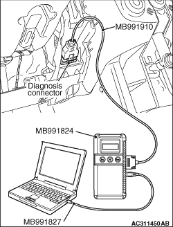
Before connecting or disconnecting the M.U.T.-III, turn the ignition switch to the "LOCK"
(OFF) position.
|
(1)Connect M.U.T.-III to the 16-pin diagnosis connector.
(2)Turn the ignition switch to the "ON" position.
(3)Diagnose the CAN bus line.
(4)Turn the ignition switch to the "LOCK" (OFF) position.
Q.
Is the check result normal?
 Go to Step 2. Go to Step 2.
 Repair the CAN bus line (Refer to GROUP 54C - CAN bus line Diagnostic
flow Repair the CAN bus line (Refer to GROUP 54C - CAN bus line Diagnostic
flow  ). ).
|
|
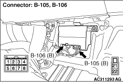
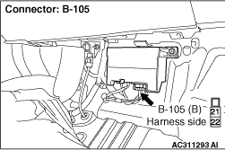
- Electric power steering-ECU connectors B-106 and B-105
Check the connectors above for improper engagement, terminal damage or terminal drawn
in the connector case.
Q.
Are the connectors and terminals in good condition?
Go to Step 3.
Repair the harness connector.
|
|
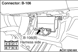
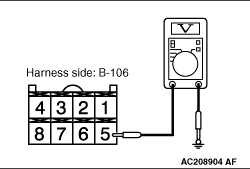
- Disconnect the connector, and measure at the wiring harness side.
- IGNITION SWITCH: ON
- Voltage between electric power steering-ECU connector B-106 terminal No.5 and body earth
OK: system voltage
Q.
Is the check result normal?
Go to Step 4.
Go to Step 6.
|
|
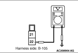
- Disconnect the connector, and measure at the wiring harness side.
- Voltage between electric power steering-ECU connector B-105 terminal No.22 and body earth
OK: system voltage
Q.
Is the check result normal?
Go to Step 5.
Go to Step 7.
|
|
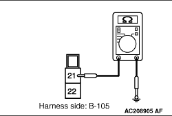
- Disconnect the connector, and measure at the wiring harness side.
- Continuity between electric power steering-ECU connector B-105 terminal No.21 and body earth
OK: Continuity exists (2 Ω or less)
Q.
Is the check result normal?
Go to Step 9.
Go to Step 8.
|
|
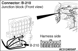
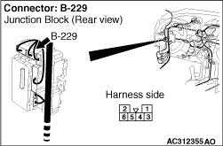
| note |
Prior to this harness wire check, check junction block connectors B-210 and B-229, and
repair if necessary.
|
|
|
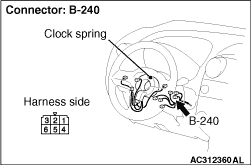
- The harness wire between electric power steering-ECU connector B106 and ignition switch (IG1)
B-240
Check the harness wire above for damage or other problem.
Q.
Is the harness wire in good condition?
Go to Step 11.
Repair the harness wire.
|
|
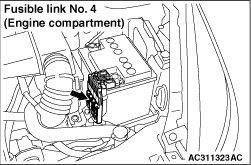
- Harness wire between electric power steering-ECU connector B-105 and fusible link No.4
Check the harness wire above for damage or other problem.
Q.
Is the harness wire in good condition?
Go to Step 11.
Repair the harness wire.
|
|
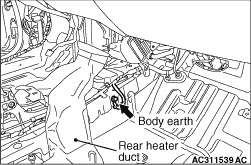
- Harness wire between electric power steering-ECU connector B-105 and body earth
Check the harness wire above for damage or other problem.
Q.
Is the harness wire in good condition?
Go to Step 11.
Repair the harness wire.
|
|
|
Refer to GROUP 54A - Battery - On-vehicle service - Battery Test.
|
|
|
Q.
Is the battery in good condition?
|
|
|
Charge or replace the battery.
|
|
|
|
|
|
Refer to GROUP 16 - Charging System - On-vehicle service - Alternator
output line voltage drop test.
|
|
|
Q.
Is the charging system in good condition?
|
|
|
Repair or replace the charging system.
|
|
|
|
|
|
Q.
Is the check result normal?
|
|
|
The malfunction is intermittent. Refer to GROUP 00 - How to Use Troubleshooting/Inspection
Service Points - How to Cope with Intermittent Malfunction .
|
|
|
|
|
|
Replace the electric power steering-ECU (Refer to ).
|
|
|
|
)
)
)
)
)
)
)
)
)
)
)
)
)
)