REMOVAL AND INSTALLATION


caution
  • Before removing the steering wheel and driver’s air bag module assembly, refer to GROUP 52B - Service Precautions and Driver’s Airbag Module Clock Spring .
  • When removing and installing the steering wheel, do not let it bump against the driver’s air bag module.
  • After adjusting the steering angle, always perform calibration to make TCL/ASC-ECU learn the neutral position of the steering wheel sensor (Refer to GROUP 35C, On-vehicle Service - Steering Wheel Sensor Calibration ). <Vehicles with TCL/ASC>
Post-installation operation
  • Steering Wheel Straight-ahead Position Check
  • Steering Wheel Play Check (Refer to ).


Removal steps
<<A>>

1.
Cover

>>B<<
2.
Horn connector connection

>>B<<
3.
Steering switch connector connection <Vehicles with steering switch connector>
<<B>>
>>B<<
4.
Driver’s air bag module connector connection
<<C>>

5.
Driver’s air bag module


6.
Steering wheel upper cover (RH) <Vehicles without cruise control switch>


7.
Steering wheel cruise control switch connector connection <Vehicles with cruise control switch>


8.
Steering wheel cruise control switch <Vehicles with cruise control switch>


9.
Steering wheel upper cover (LH) <Vehicles without steering wheel audio remote control switch>


10.
Steering wheel audio remote control switch connector connection <Vehicles with steering wheel audio remote control switch>


11.
Steering wheel audio remote control switch <Vehicles with steering wheel audio remote control switch>


12.
Flange nut
<<D>>
>>A<<
13.
Steering wheel assembly

REMOVAL SERVICE POINTS


<<A>> COVER REMOVAL


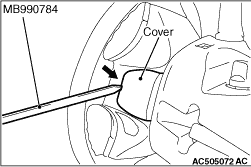
Insert the special tool ornament remover (MB990784) into the notch shown in the figure, and remove the cover.

<<B>> DRIVER’S AIR BAG MODULE CONNECTOR DISCONNECTION


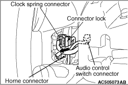
Disconnect the connector while sliding the part shown in the figure (connector lock) of the clock spring connector in the direction of an arrow.

<<C>> DRIVER’S AIR BAG MODULE REMOVAL


caution
  • Never use an electric tester to diagnose the air bag module circuit. Never attempt to disassemble the air bag module.
  • Be sure to store the removed air bag module in a clean and dry place with a pad surface facing upward.

<<D>> STEERING WHEEL ASSEMBLY REMOVAL


1.Position the steering wheel in a straight ahead direction.
caution Use the special tool to remove the steering wheel since the steering column collision absorbing mechanism may be damaged.

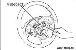
2.Use the special tool steering wheel puller (MB990803) to remove the steering wheel assembly as shown in the figure.

INSTALLATION SERVICE POINTS


>>A<< STEERING WHEEL ASSEMBLY INSTALLATION


After centring the clock spring (Refer to GROUP 52B - Air Bag Module Clock Spring ), install the steering wheel assembly.

>>B<< DRIVER’S AIR BAG MODULE CONNECTOR / STEERING SWITCH CONNECTOR/ HORN CONNECTOR CONNECTION


Connect the connector securely and route the harnesses not to lie off the cover hole.