REMOVAL AND INSTALLATION


warning Before removing the steering gear, refer to GROUP 52B - Service Precautions () and Driver’s Air Bag Module and Clock Spring (). Position the front wheels in a straight-ahead direction. Failure to do so may damage the SRS clock spring and render the SRS system inoperative, risking serious injury.
Operations before Steering Gear and Linkage Assembly Removal
  • Lower Arm Removal (Refer to GROUP 33 - Lower Arm <Except 4G1>, <4G1>).
  • Engine Roll Stopper Rod Assembly Removal (Refer to GROUP 32 - Engine Roll Stopper Rod ).
  • Driver’s Air Bag Module and Steering Wheel Assembly Removal (Refer to ).
  • Electric Power Steering-ECU Cover Removal (Refer to ).

Operations after Tie-rod End Assembly Installation
  • Push the Tie-rod End Cover with fingers and inspect for Cracks or Damage.
  • Wheel Alignment Check and Adjustment (Refer to GROUP 33 - On-vehicle Service - Front Wheel Alignment Check and Adjustment ).
Operations after Steering Gear and Linkage Assembly Installation
  • Push the Tie-rod End Cover with fingers and inspect for Cracks or Damage.
  • Electric Power Steering-ECU Cover Removal (Refer to ).
  • Confirm that the Steering Wheel is at the Straight-ahead Position.
  • Steering Wheel Assembly and Driver’s Air Bag Module Installation (Refer to ).
  • Engine Roll Stopper Rod Assembly Installation (Refer to GROUP 32 - Engine Roll Stopper Rod ).
  • Lower Arm Installation (Refer to GROUP 33 - Lower Arm <Except 4G1>, <4G1>).
  • Wheel Alignment Check and Adjustment (Refer to GROUP 33 - On-vehicle Service - Front Wheel Alignment Check and Adjustment ).


Tie-rod end removal steps
<<A>>

1.
Tie-rod end and knuckle connection


12.
Tie-rod end assembly


Steering gear and linkage assembly removal steps
<<A>>

1.
Tie-rod end and knuckle connection

>>F<<
2.
Steering gear and steering column assembly connection


·
Cowl side trim (Refer to GROUP 52A - Trim <COLT>, <COLT CZ3> ).

>>E<<
3.
Steering gear connector (in-vehicle Electric power steering-ECU)


·
Exhaust muffler hanger (Refer to GROUP 15 - Exhaust Pipe and Main Muffler <Except 4G1> or <4G1>).
<<B>>
>>D<<
4.
Front axle No.1 crossmember (Equipped with steering gear and linkage assembly, steering column dash panel cover, and stabilizer bar)


5.
Steering gear mounting crossmember plate


6.
Steering gear mounting rod side bracket


7.
Steering gear mounting bracket

>>C<<
8.
Steering gear and linkage assembly

>>B<<
9.
Steering column dash panel cover


10.
Steering gear bushing

>>A<<
11.
Steering gear cushion

REMOVAL SERVICE POINTS


<<A>> TIE-ROD END AND KNUCKLE DISCONNECTION


1.
caution
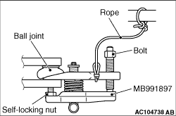
  • To prevent the ball joint thread damage, only loosen the nut from the ball joint (do not remove it), then disconnect the steering knuckle from the tie-rod using the special tool.
  • To prevent the special tool from dropping off, suspend it with a rope.
Install the ball joint remover (special tool MB991897) as shown in the figure.

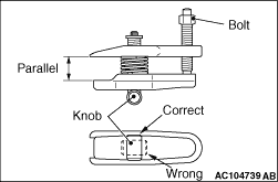
2.Turn the bolt and knob to make the special tool insert horizontal, then hand-tighten the bolt. After tightening, verify that the insert is still horizontal.
note When adjusting the special tool wedge horizontally, move the knob to the position shown in the figure so that it functions as a fulcrum of the insert.
3.Turn the bolt and disconnect the tie-rod end from the steering knuckle.

<<B>> FRONT AXLE NO.1 CROSSMEMBER (EQUIPPED WITH STEERING GEAR AND LINKAGE ASSEMBLY, STEERING COLUMN DASH PANEL COVER, AND STABILIZER BAR) REMOVAL


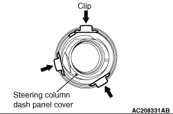
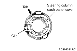
1.Remove the 3 clips (shown in the figure) from inside of the vehicle and drop the steering column dash panel cover through the body panel.
2.Remove the front axle No.1 crossmember.

INSTALLATION SERVICE POINTS


>>A<< STEERING GEAR CUSHION INSTALLATION


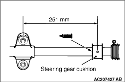
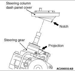
Apply the specified adhesive to the steering gear cushion and install it to the steering gear and linkage assembly as shown.
Instant adhesive: 3M ATD Part No. 1741 or equivalent

>>B<< STEERING COLUMN DASH PANEL COVER INSTALLATION


Install the steering column dash panel cover so that the cover notch is aligned with the projection of the steering gear and linkage assembly.

>>C<< STEERING GEAR AND LINKAGE ASSEMBLY INSTALLATION


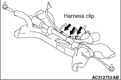
After installing the steering gear and linkage assembly to the front axle No.1 crossmember, secure the 3 harness clips of the steering gear and linkage assembly to the front axle No.1 crossmember.

>>D<< FRONT AXLE NO.1 CROSSMEMBER (EQUIPPED WITH STEERING GEAR AND LINKAGE ASSEMBLY, STEERING COLUMN DASH PANEL COVER, AND STABILIZER BAR) INSTALLATION


After installing the front axle No.1 crossmember to the body, pull the steering column dash panel cover tab (shown in the figure) from inside of the vehicle and secure the 3 clips to the body panel.

>>E<< STEERING GEAR CONNECTOR (IN-VEHICLE ELECTRIC POWER STEERING-ECU) INSTALLATION


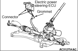
Firmly secure the grommet to the body panel and connect the connector to the Electric power steering-ECU.

>>F<< STEERING GEAR AND STEERING COLUMN ASSEMBLY CONNECTION


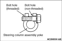
Insert the steering column bolt into the non-threaded bolt hole.