Code No.C1863:
G and yaw rate sensor power voltage malfunction (low voltage)
|
|
| caution |
- If there is
any problem in the CAN bus lines, an incorrect diagnosis code may be set. Prior to this diagnosis,
diagnose the CAN bus lines (Refer to GROUP 54C, CAN Bus Diagnosis Table
 ). ).
- Whenever ECU is replaced, ensure that the CAN bus lines are normal.
|
|
|
|
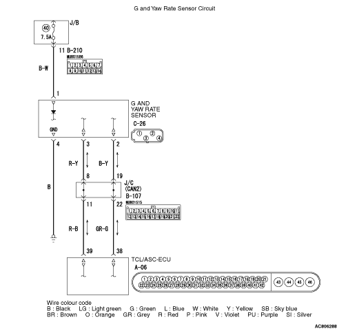
The G and yaw rate sensor output signal is sent to TCL/ASC-ECU via the CAN bus
lines.
|
|
|
DIAGNOSIS CODE SET CONDITIONS
|
|
|
The G and yaw rate sensor monitors the power supply voltage supplied from the IG1, and
if the sensor determines that the voltage value is abnormally low, it sets this code.
|
|
|
- Damaged harness wires and connectors
- Charging circuit failure
- Malfunction of the G and yaw rate sensor
|
|
|
STEP 1. M.U.T.-III CAN bus diagnostics
|
|
|
Use the M.U.T.-III to diagnose the CAN bus lines.
|
|
|
Q.
Is the check result normal?
|
|
|
 Go to Step 3. Go to Step 3.
|
|
|
|
|
|
 Repair the CAN bus lines. (Refer to GROUP 54C - Troubleshooting .)
On completion, go to Step 2. Repair the CAN bus lines. (Refer to GROUP 54C - Troubleshooting .)
On completion, go to Step 2.
|
|
|
|
|
|
STEP 2. Diagnosis code recheck after resetting CAN bus lines
|
|
|
Q.
Is the diagnosis code No.C1863 set?
|
|
|
Go to Step 3.
|
|
|
|
|
|
This diagnosis is complete.
|
|
|
|
|
|
STEP 3. Battery terminal voltage measurement
|
|
|
(2)Measure the voltage between the positive and negative battery terminals.
OK: 10 V or more
|
|
|
Q.
Is the check result normal?
|
|
|
Go to Step 4.
|
|
|
|
|
|
Diagnose the charging system. (Refer to GROUP 16 - On-vehicle Service .)
|
|
|
|
|
|
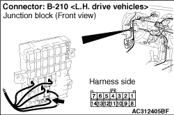
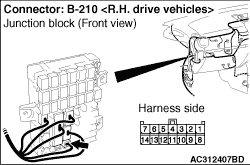
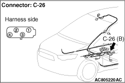
STEP 4. Connector check: C-26 G and yaw rate sensor connector, B-210
junction block connector
|
|
Q.
Is the check result normal?
Go to Step 5.
Repair the damaged connector.
|
|
|
STEP 5. Voltage measurement at C-26 G and yaw rate sensor connector
|
|
(1)Disconnect the C-26 G and yaw rate sensor connector, and measure at the harness
side connector.
|
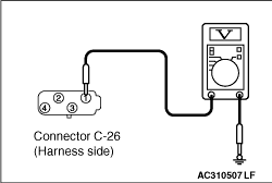
|
(2)Measure the voltage at the C-26 G and yaw rate sensor connector terminal No.1 and body
earth.
OK: 9 V or more
Q.
Is the check result normal?
Go to Step 7.
Go to Step 6.
|
|
|
STEP 6. Check the wiring harness between C-26 G and yaw rate sensor
connector and B-210 junction block connector.
|
|
(1)Disconnect the C-26 G and yaw rate sensor connector and the B-210 junction block
connector, and measure at the harness side connector.
|
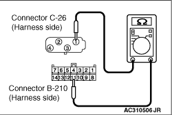
|
(2)Measure the resistance at the C-26 G and yaw rate sensor connector terminal No.1 and B-210
junction block connector terminal No.11.
OK: Continuity exists (2 Ω or less)
Q.
Is the check result normal?
Go to Step 7.
Repair the wiring harness.
|
|
|
STEP 7. Resistance measurement at C-26 G and yaw rate sensor connector
|
|
(1)Disconnect the C-26 G and yaw rate sensor connector, and measure at the harness
side connector.
|
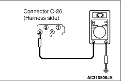
|
(2)Measure the resistance at the C-26 G and yaw rate sensor connector terminal No.4 and body
earth.
OK: Continuity exists (2 Ω or less)
Q.
Is the check result normal?
Go to Step 8.
Repair the wiring harness.
|
|
|
STEP 8. Diagnosis code recheck
|
|
|
Check again if the diagnosis code is set.
|
|
|
(1)Erase the diagnosis code.
|
|
|
(2)Ignition switch: "LOCK" (OFF)
|
|
|
Q.
Is the diagnosis code No.C1863 set?
|
|
|
Replace the G and yaw rate sensor (Refer to ).
|
|
|
|
|
|
Intermittent malfunction (Refer to GROUP 00 - How to Cope with Intermittent
Malfunction ).
|
|
|
|
)
)
)
)
)
)
)