|
|
TCL/ASC-ECU monitors the ON/OFF signals from the stop lamp switches
(brake control system and cruise control system) and the pressure sensor (incorporated in the hydraulic
unit).
|
|
|
This diagnosis code is set in the following case.
|
|
|
- When both of the signals from the stop lamp switches (brake control system
and cruise control system) are ON.
- When the signal that the brake pressure is applied is received from the pressure
sensor (incorporated in the hydraulic unit) although the signal from the stop lamp switch (brake
control system) is OFF.
|
|
|
- Improper adjustment of stop lamp switch installation position
- Stop lamp switch malfunction
- Damaged wiring harness and connectors
- TCL/ASC-ECU malfunction
|
|
|
Use M.U.T.-III to diagnose the CAN bus lines.
|
|
|
Q.
Is the check result normal?
|
|
|
 Repair the CAN bus lines. (Refer to GROUP 54C - CAN Bus Diagnosis table Repair the CAN bus lines. (Refer to GROUP 54C - CAN Bus Diagnosis table  .)
On completion, go to Step 2. .)
On completion, go to Step 2.
|
|
|
|
|
|
Q.
Is diagnosis code No.C1340 set?
|
|
|
This diagnosis is complete.
|
|
|
|
|
|
Refer to GROUP 54A - Battery Test .
|
|
|
Q.
Is the battery in good condition?
|
|
|
Charge or replace the battery. Then go to Step 23.
|
|
|
|
|
|
Check the stop lamp operation when the brake pedal is depressed. Check that all the stop
lamp illuminates when the brake pedal is depressed and that it goes out when the brake pedal
is released.
|
|
|
OK:
When the brake pedal is released: OFF
When the brake pedal is depressed: Illuminates
|
|
|
Q.
Is the check result normal?
|
|
|
Refer to GROUP 35A - On-vehicle Service .
|
|
|
Q.
Is the check result normal?
|
|
|
Install the stop lamp switch correctly. (Refer to GROUP 35A - On-vehicle
Service .) Then go to Step 23.
|
|
|
|
|
|
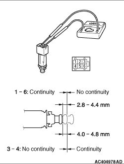
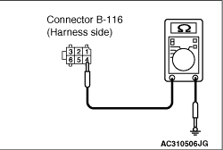
(1)Remove the stop lamp switch. (Refer to GROUP 35A - Brake Pedal .)
|
|
(2)Connect the circuit tester (Ω range) to the stop lamp switch connector terminals
No.1 and 6 or No. 3 and 4.
(3)Check for continuity between the terminals of the switch.
|
|
Check condition
|
Terminal connector of tester
|
Normal condition
|
When the switch knob is depressed fully
|
1 - 6
|
Continuity exists
(2 Ω or less)
|
3 - 4
|
No continuity
|
When the switch knob is returned 2.8 mm or more
|
1 - 6
|
No continuity
|
When the switch knob is returned 4 mm or more
|
3 - 4
|
Continuity exists
(2 Ω or less)
|
|
Q.
Is the check result normal?
 Go to Step 7. Go to Step 7.
Replace the stop lamp switch. (Refer to GROUP 35A - Brake Pedal .)
Then go to Step 23.
|
|
|
Q.
Is the check result normal?
|
|
Q.
Is the check result normal?
Go to Step 9.
Repair the damaged connector, and then replace fuse No.42. Then go to Step 23
.
|
|
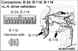
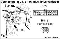
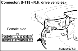
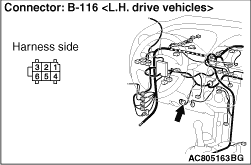
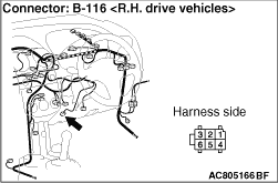
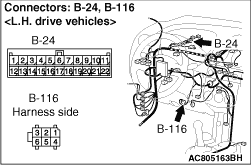
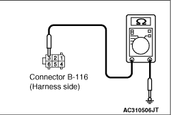
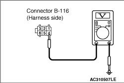
(1)Disconnect B-116 stop lamp switch connector, and measure at the wiring harness side.
|
|
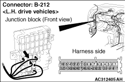
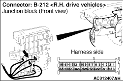
(2)Disconnect B-212 junction block connector.
|
|
(3)Measure the resistance between the terminal No.4 and the body earth.
OK: No continuity
Q.
Is the check result normal?
Go to Step 10.
An short to power supply line may be present in the wiring harness between B-212
junction block connector terminal No.22 and B-116 stop lamp switch connector terminal No.4.
Repair the wiring harness, and then replace fuse No.42. Then go to Step 23.
|
|
(1)Disconnect B-116 stop lamp switch connector, and measure at the wiring harness side.
|
|
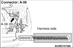
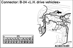
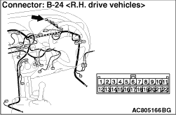
(2)Disconnect A-06 TCL/ASC-ECU connector and B-24 joint connector.
|
|
(3)Measure the resistance between the terminal No.3 and the body earth.
OK: No continuity
Q.
Is the check result normal?
Go to Step 11.
An short circuit may be present in the wiring harness between B-116 stop lamp
switch connector terminal No.3 and A-06 TCL/ASC-ECU connector terminal No.6, or between B-116
stop lamp switch connector terminal No.3 and B-24 joint connector terminal No.11. Repair the
wiring harness, and then replace fuse No.42. Then go to Step 23.
|
|
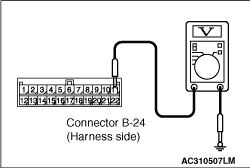
(1)Disconnect B-24 joint connector, and measure at the wiring harness side.
|
|
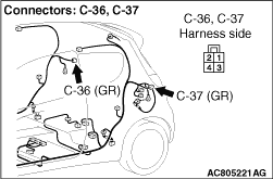
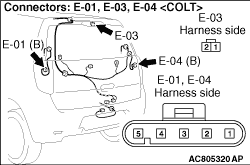
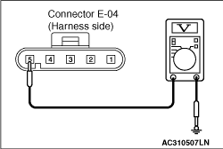
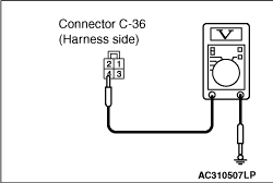
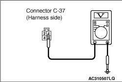
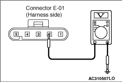
(2)Disconnect E-04 rear combination lamp (stop: RH) connector <COLT>, C-36
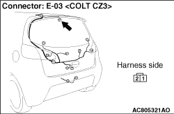
rear combination lamp (stop: RH) connector <COLT CZ3>, E-01 rear combination
lamp (stop: LH) connector <COLT>, C-37 rear combination lamp (stop: LH) connector <COLT
CZ3>, E-03 highmounted stop lamp connector.
|
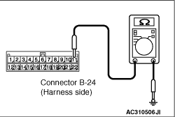
|
(3)Measure the resistance between the terminal No.11 and the body earth.
OK: No continuity
Q.
Is the check result normal?
Replace fuse No.42. Then go to Step 23.
An short circuit may be present in the wiring harness between B-24 joint connector
terminal No.11 and E-04 rear combination lamp (stop: RH) connector terminal No.5 <COLT> or
C-36 rear combination lamp (stop: RH) connector terminal No.4 <COLT CZ3> or E-01
rear combination lamp (stop: LH) connector terminal No.2 <COLT> or C-37 rear combination
lamp (stop: LH) connector terminal No.1 <COLT CZ3> or E-03 highmounted stop
lamp connector terminal No.2. Repair the wiring harness, and then replace fuse No.42. Then go
to Step 23.
|
|
Q.
Is the check result normal?
Go to Step 13.
Repair the damaged connector. Then go to Step 23.
|
|
| caution |
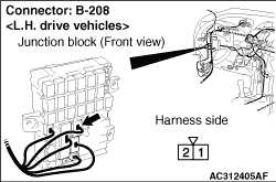
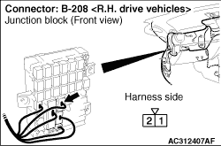
Measure while the brake pedal is not depressed.
|
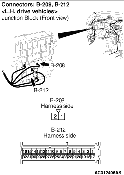
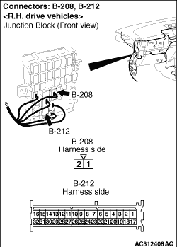
Measure the voltage between terminal No. 1 and the body earth by backprobing.
OK: System voltage
Q.
Is the check result normal?
Go to Step 14.
An open circuit may be present in the wiring harness between B-208 junction block
connector terminal No.1 and fusible link No.1. Repair the wiring harness. Then go to Step 23
.
|
|
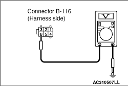
(1)Disconnect B-116 stop lamp switch connector, and measure the voltage at harness
connector side.
|
|
(2)Measure the voltage between the terminal No.4 and the body earth.
OK: System voltage
Q.
Is the check result normal?
Go to Step 15.
An open circuit may be present in the wiring harness between B-116 stop lamp switch
connector terminal No.4 and B-212 junction block connector terminal No. 22. Repair the wiring
harness. Then go to Step 15.
|
|
(1)Disconnect B-24 joint connector, and measure the voltage at harness connector side.
|
|
(2)Measure the voltage between the terminal No.11 and the body earth.
OK: System voltage
Q.
Is the check result normal?
Go to Step 16.
An open circuit may be present in the wiring harness between B-116 stop lamp switch
connector terminal No.3 and B-24 joint connector terminal No. 11. Repair the wiring harness.
Then go to Step 16.
|
|
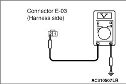
(1)Disconnect E-04 rear combination lamp (stop: RH) connector <COLT>,
C-36 rear combination lamp (stop: RH) connector <COLT CZ3>, E-01 rear combination
lamp (stop: LH) connector <COLT>, C-37 rear combination lamp (stop: LH) connector <COLT
CZ3>, E-03 highmounted stop lamp connector, and measure the voltage at harness connector
side.
|
|
(2)Measure the voltage between the E-04 rear combination lamp (stop: RH) connector terminal
No.5 <COLT>, C-36 rear combination lamp (stop: RH) connector terminal No.4 <COLT
CZ3>, E-01 rear combination lamp (stop: LH) connector terminal No.2 <COLT>,
C-37 rear combination lamp (stop: LH) connector terminal No.1 <COLT CZ3>,
E-03 highmounted stop lamp connector terminal No.2 and the body earth.
OK: System voltage
Q.
Is the check result normal?
Go to Step 18.
An open circuit may be present in the wiring harness between B-24 junction connector
terminal No.8, 9 10 and E-04 rear combination lamp (stop: RH) connector terminal No.5 <COLT>,
C-36 rear combination lamp (stop: RH) connector terminal No.4 <COLT CZ3>,
E-01 rear combination lamp (stop: LH) connector terminal No.2 <COLT>, C-37
rear combination lamp (stop: LH) connector terminal No.1 <COLT CZ3>, E-03
highmounted stop lamp connector terminal No.2. Repair the wiring harness. Then go to Step 23
.
|
|
Q.
Is the check result normal?
Go to Step 18.
Repair the damaged connector. Then go to Step 23.
|
|
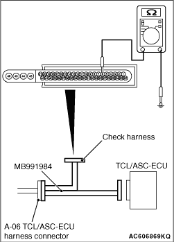
(1)Disconnect the TCL/ASC-ECU connector, connect special tool ABS check harness (MB991951)
to the harness-side connector, and then measure the voltage at the special tool connector side.
| note |
Do not connect the special tool ABS check harness (MB991951) to TCL/ASC-ECU.
|
(2)Turn the ignition switch to the ON position.
|
|
(3)Measure the voltage between the terminal No.6 and the body earth.
OK:
When the brake pedal is released: 1 V or less
When the brake pedal is depressed: System voltage
Q.
Is the check result normal?
Go to Step 19.
An open circuit may be present in the wiring harness between B-116 stop lamp switch
connector terminal No.3 and A-06 TCL/ASC-ECU connector terminal No.6. Repair the wiring harness.
Then go to Step 23.
|
|
(1)Disconnect B-116 stop lamp switch connector, and measure the voltage at harness
connector side.
(2)Turn the ignition switch to the ON position.
|
|
(3)Measure the voltage between the terminal No.6 and the body earth.
OK: System voltage
Q.
Is the check result normal?
Go to Step 21.
An open circuit may be present in the wiring harness between B-116 stop lamp switch
connector terminal No.6 and A-06 TCL/ASC-ECU connector terminal No. 23. Repair the wiring harness.
Then go to Step 20.
|
|
(1)Disconnect B-116 stop lamp switch connector, and measure at the wiring harness side.
|
|
(2)Disconnect A-06 TCL/ASC-ECU connector.
|
|
(3)Measure the resistance between the terminal No.6 and the body earth.
OK: No continuity
Q.
Is the check result normal?
Go to Step 21.
An short circuit may be present in the wiring harness between B-116 stop lamp
switch connector terminal No.6 and A-06 TCL/ASC-ECU connector terminal No.23. Repair the wiring
harness. Then go to Step 21.
|
|
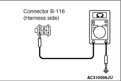
(1)Disconnect B-116 stop lamp switch connector, and measure at the wiring harness side.
|
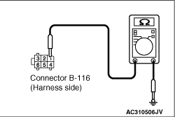
|
(2)Measure the resistance between the terminal No.1 and the body earth.
OK: Continuity
Q.
Is the check result normal?
Go to Step 22.
An open circuit may be present in the wiring harness between B-116 stop lamp switch
connector terminal No.1 and body earth. Replace the wiring harness. Then go to Step 23.
|
|
|
Q.
Is diagnosis code No.C1340 set?
|
|
|
Replace the hydraulic unit (TCL/ASC-ECU) (Refer to ). Then
go to Step 23.
|
|
|
|
|
|
Intermittent malfunction (Refer to GROUP 00 - How to Cope with Intermittent
Malfunction .)
|
|
|
|
|
|
Q.
Is diagnosis code No.C1340 set?
|
|
|
This diagnosis is complete.
|
|
|
|
)
)
)
)
)
)
)
)
)
)
)
)
)
)
)
)
)
)
)
)
)
)
)
)
)
)
)
)
)
)
)
)
)
)