|
|
- The TCL/ASC-ECU is energized by the ignition switch (IG1) through
multi-purpose fuse No.40 and the TCL/ASC-ECU terminal No.40.
- If the power supply to the TCL/ASC-ECU has failed, M.U.T.-III will not be able to
communicate with it.
|
|
|
- Damaged wiring harness or connector
- Defective battery
- Charging system failed
- Malfunction of the hydraulic unit (integrated with TCL/ASC-ECU)
|
|
|
(3)Measure the voltage between the battery terminals.
OK: more than 10 V
|
|
|
Q.
Is the check result normal?
|
|
|
 Diagnose the charging system (Refer to GROUP 16, Charging System - On-vehicle
Service Diagnose the charging system (Refer to GROUP 16, Charging System - On-vehicle
Service  ). ).
|
|
|
|
|
Q.
Is the check result normal?
 Go to Step 3. Go to Step 3.
Repair the defective connector.
|
|
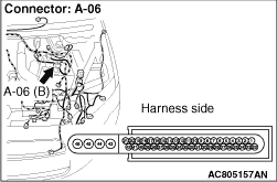
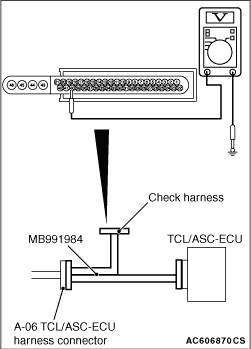
(1)Disconnect the A-06 TCL/ASC-ECU connector, and connect special tool ABS Check Harness
(MB991984) to the wiring harness-side connector.
| note |
Connect special tool ABS Check Harness (MB991984) to the TCL/ASC-ECU.
|
(2)Ignition switch: "ON"
(3)Engine: Started
|
|
(4)Voltage between special tool ABS Check Harness (MB991984) connector terminal No.40 and
body earth
OK: More than 10 V
Q.
Is the check result normal?
Go to Step 4.
Repair the wiring harness between A-06 TCL/ASC-ECU connector terminal No. 40 and
the ignition switch (IG1).
|
|
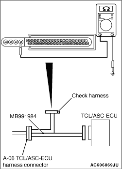
(1)Disconnect the A-06 TCL/ASC-ECU connector, and connect special tool ABS Check Harness
(MB991984) to the wiring harness-side connector.
| note |
Do not connect special tool ABS Check Harness (MB991984) to the TCL/ASC-ECU.
|
|
|
(2)Measure the resistance between the A-06 TCL/ASC-ECU connector terminal No.43 and body
earth and between the A-06 TCL/ASC-ECU connector terminal No.46 and body earth.
OK: Continuity exists (2 Ω or less)
Q.
Is the check result normal?
Go to Step 5.
Repair the wiring harness between A-06 TCL/ASC-ECU connector terminal No.43 and
body earth.
|
|
|
Q.
Can the TCL/ASC-ECU communicate with the M.U.T.-III?
|
|
|
It can be assumed that this malfunction is intermittent. Refer to GROUP 00, How
to Use Troubleshooting/Inspection Service Points - How to Cope with Intermittent
Malfunction .
|
|
|
|
|
|
Replace the hydraulic unit (integrated with TCL/ASC-ECU). Then perform the variant
coding and write the VIN data (Refer to GROUP 00, Precautions Before Service - How
to Perform Variant Coding ).
|
|
|
|
)
)
)
)