|
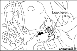
1.Operate the lock lever to disconnect the TCL/ASC-ECU harness connector as shown
in the figure.
|
|
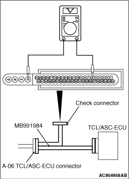
2.Connect the special tool ABS check harness (MB991984) to measure the voltage between each
check connector terminal and the earth terminal (No.43 or 46).
Terminal No.
|
Check item
|
Check condition
|
Normal condition
|
6
|
Stop lamp switch signal (Stop lamp)
|
Stop lamp switch: OFF (Brake pedal is not depressed)
|
1 V or less
|
Stop lamp switch: ON (Brake pedal is depressed)
|
System voltage
|
23
|
Stop lamp switch signal (Brake switch)
|
- Ignition switch: ON
- Stop lamp switch: OFF (Brake pedal is depressed)
|
System voltage
|
- Ignition switch: ON
- Stop lamp switch: ON (Brake pedal is not depressed)
|
1 V or less
|
32
|
Brake fluid level switch signal
|
- Ignition switch: ON
- Brake fluid level: specified value (lower level) or more
|
System voltage
|
- Ignition switch: ON
- Brake fluid level: specified value (lower level) or less
|
1 V or less
|
30
|
Wheel speed sensor (RR) power supply
|
Ignition switch: ON
|
System voltage
|
29
|
Wheel speed sensor (FR) power supply
|
Ignition switch: ON
|
System voltage
|
11
|
Wheel speed sensor (RL) power supply
|
Ignition switch: ON
|
System voltage
|
27
|
Parking brake switch signal
|
- Ignition switch: ON
- When the parking brake lever is not operated (The parking brake lever is released).
|
System voltage
|
- Ignition switch: ON
- When the parking brake lever is operated (The parking brake lever is pulled).
|
1 V or less
|
40
|
TCL/ASC-ECU power supply
|
Ignition switch: ON
|
System voltage
|
Ignition switch: OFF
|
1 V or less
|
34
|
Wheel speed sensor (FL) power supply
|
Ignition switch: ON
|
System voltage
|
44
|
Solenoid valve power supply
|
Ignition switch: ON (OFF)
|
System voltage
|
45
|
Motor power supply
|
Ignition switch: ON (OFF)
|
System voltage
|
|
|
1.Operate the lock lever to disconnect the TCL/ASC-ECU harness connector as shown
in the figure.
|
|
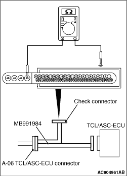
2.When performing the continuity check, turn the ignition switch to "LOCK" (OFF) position,
connect the special tool ABS check harness (MB991984) as shown in the figure, and disconnect the
ASC-ECU connector.
3.Check the continuity between terminals shown in the chart below.
4.Terminal layout is shown in the figure.
Terminal No.
|
Signal
|
Normal condition
|
43 - body earth
|
Earth
|
Continuity exists (2 Ω or less)
|
46 - body earth
|
Earth
|
Continuity exists (2 Ω or less)
|
|
)
)
)