Code No.C1210:
Abnormality in RR wheel speed sensor circuit
|
|
| caution |
If there is any problem in
the CAN bus lines, an incorrect diagnosis code may be set. Prior to this diagnosis, diagnose
the CAN bus lines (Refer to GROUP 54C, Trouble code diagnosis  ). ).
|
|
|
|
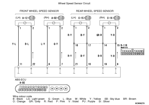
- The wheel speed sensor is a kind of a pulse generator.
It consists of encoders (a plate on which north and south pole sides of the magnets are arranged
alternately) for detecting the wheel speed which rotates at the same speed of the wheels and
wheel speed sensors. This sensor outputs frequency pulse signals in proportion to the wheel
speed.
- The pulse signals, which the wheel speed sensor creates, are sent to ABS-ECU. ABS-ECU
uses the frequency of the pulse signals to determine the wheel speed.
|
|
|
DIAGNOSIS CODE SET CONDITIONS
|
|
|
ABS-ECU monitors the voltage fluctuation in each wheel speed sensor circuit. If ABS-ECU
detects the open or short circuit in the circuit, it will set a diagnosis code.
|
|
|
Current trouble
- Damaged wiring harness and connectors
- Noise interference
- Malfunction of wheel speed sensor
- ABS-ECU malfunction
|
|
|
Past trouble
- Carry out diagnosis with particular emphasis on wiring harness and
connector failures between ABS-ECU and the wheel speed sensor. For diagnosis procedures, refer
to How to treat past trouble (GROUP 00 - How to Cope with Intermittent Malfunction ).
|
|
|
STEP 1. M.U.T.-III CAN bus diagnosis
|
|
|
Use M.U.T.-III to diagnose the CAN bus lines.
|
|
|
Q.
Is the check result normal?
|
|
|
 Go to Step 3. Go to Step 3.
|
|
|
|
|
|
 Repair the CAN bus lines (Refer to GROUP 54C - CAN Bus Diagnosis table ).
On completion, go to Step 2. Repair the CAN bus lines (Refer to GROUP 54C - CAN Bus Diagnosis table ).
On completion, go to Step 2.
|
|
|
|
|
|
STEP 2. Diagnosis code recheck after resetting CAN bus lines
|
|
|
Q.
Is the diagnosis code No.C1210 set?
|
|
|
Go to Step 3.
|
|
|
|
|
|
The procedure is complete.
|
|
|
|
|
|
STEP 3. M.U.T.-III data list
|
|
|
Check the following data list (Refer to ).
|
|
|
- Item No.04: RR wheel speed sensor
|
|
|
Q.
Is the check result normal?
|
|
|
Go to Step 12.
|
|
|
|
|
|
Go to Step 4.
|
|
|
|
|
|
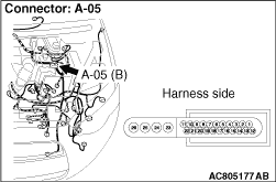
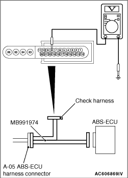
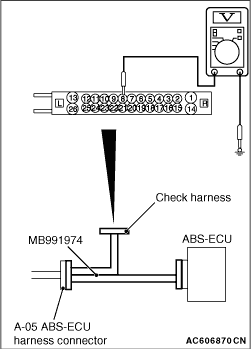
STEP 4. Voltage measurement at the A-05 ABS-ECU connector
|
|
(1)Disconnect the ABS-ECU connector, connect special tool ABS check harness (MB991951)
to the harness-side connector, and then measure the voltage at the special tool connector side.
| note |
Do not connect the special tool ABS check harness (MB991951) to ABS-ECU.
|
(2)Turn the ignition switch to the ON position.
|
|
(3)Measure the voltage between the rear wheel speed sensor <RH> power supply
terminal (signal terminal) No.8 and the body earth, and between the rear wheel speed sensor <RH> earth
terminal No.19 and the body earth.
OK: 1 volt or less
Q.
Is the check result normal?
Go to Step 5.
NO (Not normal at the terminal No.8 or 19) : Go to Step 6. : Go to Step 6.
|
|
|
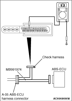
STEP 5. Resistance measurement at A-05 ABS-ECU connector
|
|
(1)Disconnect the ABS-ECU connector, connect special tool ABS check harness (MB991951)
to the harness-side connector, and then measure the resistance at the special tool connector
side.
| note |
Do not connect the special tool ABS check harness (MB991951) to ABS-ECU.
|
|
|
(2)Resistance between the rear wheel speed sensor <RH> power supply terminal
(signal terminal) No.8 and the body earth, and between the rear wheel speed sensor <RH> earth
terminal No.19 and the body earth.
OK: No continuity
Q.
Is the check result normal?
Go to Step 8.
NO (Not normal at the terminal No.8 or 19) : Go to Step 6.
|
|
|
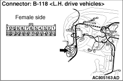
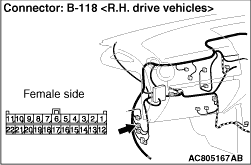
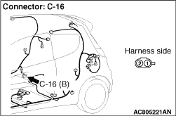
STEP 6. Connector check: A-05 ABS-ECU connector, B-118 intermediate
connector, C-16 rear wheel speed sensor <RH> connector
|
|
Q.
Is the check result normal?
Go to Step 7.
Repair the defective connector. Then go to Step 13.
|
|
|
STEP 7. Wiring harness check between A-05 ABS-ECU connector terminal
No.8 and C-16 rear wheel speed sensor <RH> connector terminal No.2, and between
A-05 ABS-ECU connector terminal No.19 and C-16 rear wheel speed sensor <RH> connector
terminal No.1.
|
|
- Check for short circuit in rear wheel speed sensor <RH> circuit
Q.
Is the check result normal?
Replace the wheel speed sensor <RR> (Refer to ).
Then go to Step 13.
Repair the wiring harness. Then go to Step 13.
|
|
|
STEP 8. Voltage measurement at the A-05 ABS-ECU connector
|
|
(1)Disconnect the ABS-ECU connector, connect special tool ABS check harness (MB991951)
to the ABS-ECU-side connector and harness-side connector, and then measure the voltage at the
special tool connector side.
(2)Turn the ignition switch to the ON position.
|
|
(3)Measure the voltage between the rear wheel speed sensor <RH> circuit
power supply terminal (signal terminal) No.8 and the body earth and between the rear wheel speed sensor <RH> circuit
earth terminal No.19 and the body earth.
Voltage between terminal No.8 and body earth
Voltage between terminal No.19 and body earth
Q.
Is the check result normal?
Go to Step 12.
Go to Step 9.
|
|
|
STEP 9. Wiring harness check between A-05 ABS-ECU connector terminal
No.8 and C-16 rear wheel speed sensor <RH> connector terminal No.2, and between
A-05 ABS-ECU connector terminal No.19 and C-16 rear wheel speed sensor <RH> connector
terminal No.1.
|
|
- Check for open circuit in rear wheel speed sensor <RH> circuit.
Q.
Is the check result normal?
Go to Step 10.
Repair the wiring harness. Then go to Step 13.
|
|
|
STEP 10. Check for wheel speed sensor <RR> as a single
unit
|
|
|
Refer to .
|
|
|
Q.
Is the check result normal?
|
|
|
Go to Step 11.
|
|
|
|
|
|
Replace the wheel speed sensor <RR> (Refer to ).
Then go to Step 13.
|
|
|
|
|
|
STEP 11. Connector check: A-05 ABS-ECU connector, B-118 intermediate
connector, C-16 wheel speed sensor <RH> connector
|
|
Q.
Is the check result normal?
Go to Step 12.
Repair the defective connector. Then go to Step 13.
|
|
|
STEP 12. Check whether the diagnosis code is reset.
|
|
|
(1)Turn the ignition switch to the "ON" position.
|
|
|
(2)Erase the diagnosis code.
|
|
|
(3)Turn the ignition switch to the "LOCK" (OFF) position.
|
|
|
(4)Turn the ignition switch to the "ON" position.
|
|
|
(5)Drive the vehicle at 10 km/h or more.
|
|
|
(6)Check if the diagnosis code is set.
|
|
|
Q.
Is the diagnosis code No.C1210 set?
|
|
|
Replace the hydraulic unit (integrated with ABS-ECU) (Refer to ).
Then go to Step 13.
|
|
|
|
|
|
Intermittent malfunction (Refer to GROUP 00 - How to Cope with Intermittent
Malfunction ).
|
|
|
|
|
|
STEP 13. Check whether the diagnosis code is reset.
|
|
|
(1)Turn the ignition switch to the "ON" position.
|
|
|
(2)Erase the diagnosis code.
|
|
|
(3)Turn the ignition switch to the "LOCK" (OFF) position.
|
|
|
(4)Turn the ignition switch to the "ON" position.
|
|
|
(5)Drive the vehicle at 10 km/h or more.
|
|
|
(6)Check if the diagnosis code is set.
|
|
|
Q.
Is the diagnosis code No.C1210 set?
|
|
|
Return to Step 1.
|
|
|
|
|
|
This diagnosis is complete.
|
|
|
|
)
)
)
)
)
)
)
)