|
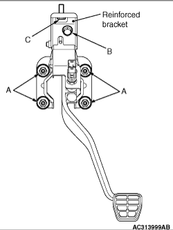
1.Install the reinforced bracket on the vehicle side by the bolt "C" temporarily.
2.Install the brake pedal and pedal support member, and tighten the nut "A" to the specified torque.
3.Tighten the bolt "B" connecting the brake pedal and pedal support member with the
reinforced bracket to the specified torque.
4.Tighten the bolt "C" to the specified torque.
5.Repeat the pedal operation over several times and check that it is in good condition.
|
|
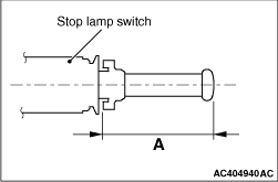
1.Hold the end of stop lamp switch and draw out the ratchet control mechanism, which is
incorporated in the stop lamp switch.
| note |
The ratchet mechanism is 8 mm, and the A shown can extend until minimum 24 mm.
|
2.Push the stop lamp switch into the brake pedal support member and turn it right while
holding the brake pedal by hand so that it is not pushed.
| note |
At this time, the control mechanism incorporated in the stop lamp switch shrinks and becomes
the standard position.
|
|
 ).
).)
)
)