REMOVAL AND INSTALLATION <Except 4G1>


caution
  • Before removing the steering wheel and driver’s air bag module assembly, refer to GROUP 52B - Service Precautions and Driver’s Air Bag Module and Clock Spring . Also, put the front wheels in straight-ahead position. Failure to do so may damage the SRS clock spring and render the SRS air bag inoperative, which results serious driver injury.
Pre-removal Operation
  • Steering Wheel and Driver’s Air Bag Module Assembly Removal (Refer to GROUP 37 - Steering Wheel ).
  • Engine Roll Stopper Rod Assembly (Refer to GROUP 32 - Engine Roll Stopper Rod ).
  • Front Exhaust Pipe Removal (Refer to GROUP 15 - Exhaust Pipe and Main Muffler ).

Post-installation Operation
  • Front Exhaust Pipe Installation (Refer to GROUP 15 - Exhaust Pipe and Main Muffler ).
  • Engine Roll Stopper Rod Assembly (Refer to GROUP 32 - Engine Roll Stopper Rod ).
  • Steering Wheel and Driver’ Air Bag Module Assembly Installation (Refer to GROUP 37 - Steering Wheel ).
  • Check the Dust Covers for Cracks or Damage by Pushing it with Your Finger.
  • Checking Steering Wheel Position with Wheels Straight Ahead.
  • Front Wheel Alignment Check and Adjustment (Refer to ).


Removal steps

>>D<<
1.
Stabilizer link bush (A)

>>D<<
2.
Stabilizer link bush (B)

>>D<<
3.
Stabilizer link bush inner

>>C<<
4.
Fixture

>>C<<
5.
Bushing


6.
Lower arm assembly (Refer to ).

>>B<<
7.
Steering gear connector (vehicle with EPS-ECU)
<<A>>
>>A<<
8.
Bolt (steering gear and steering column assembly connection)
<<B>>

9.
Front axle No.1 crossmember
<<B>>

10.
Stabilizer bar

REMOVAL SERVICE POINTS


<<A>> BOLT (STEERING GEAR AND STEERING COLUMN ASSEMBLY) DISCONNECTION


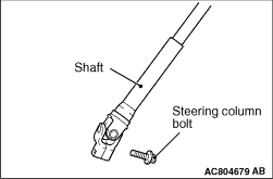
Remove the bolt connecting the steering gear to the steering column assembly.

<<B>> FRONT AXLE NO.1 CROSSMEMBER/ STABILIZER BAR REMOVAL


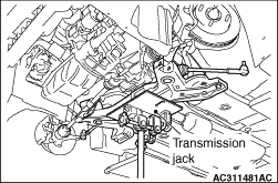
Carry out the following operations to ensure working space in order to remove the stabilizer bar.

1.Use a transmission jack to hold the crossmember, and then remove the crossmember mounting nuts and bolts.
2.
caution Be careful not to lower the crossmember excessively, otherwise the power steering return hose bracket may deform.
Lower the crossmember until the stabilizer bar can be removed.

INSTALLATION SERVICE POINTS


>>A<< BOLT (STEERING GEAR AND STEERING COLUMN ASSEMBLY) CONNECTION


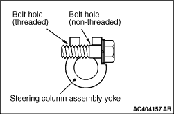
Insert the bolt connecting the steering column assembly with the steering gear into the non-threaded bolt hole.

>>B<< STEERING GEAR CONNECTOR (VEHICLE WITH EPS-ECU) INSTALLATION


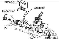
Firmly secure the grommet to the body panel and connect the connector to the EPS-ECU.

>>C<< BUSHING/ FIXTURE INSTALLATION


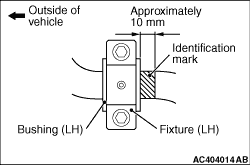
Align the stabilizer bar identification mark with the right end of the bushing (LH).

>>D<< STABILIZER LINK BUSH INNER/STABILIZER LINK BUSH (B)/STABILIZER LINK BUSH (A) INSTALLATION


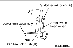
Install the stabilizer link bush inner, stabilizer link bush (B) and stabilizer link bush (A) as shown in the figure, and tighten the stabilizer link bush (A) so that the protruding length of the stabilizer link bolt meets its standard value (A).
Standard value (A): 22 ± 1.5 mm