|
1.
| caution |
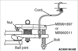
- Do not remove the self-lock nut from the
ball joint, but only loosen it, and use the special tool.
- To prevent the special tool from dropping off, suspend it with a cord.
|
Install special tool ball joint remover (MB991897or MB992011) as shown in the figure.
|
|
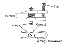
2.Turn the bolt and knob to make the special tool jaws parallel, then hand-tighten the bolt.
After tightening, check that the jaws are still parallel.
| note |
To adjust the special tool jaws to be parallel, set the knob as shown in the figure so
that it functions as a fulcrum of the jaws.
|
3.Turn the bolt and disconnect the tie-rod end from the steering knuckle.
|
|
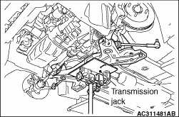
1.Use a transmission jack to hold the front axle No.1 crossmember, and then remove the crossmember
mounting bolts.
2.Lower the front axle No.1 crossmember with the stabilizer bar and the steering gear.
|
|
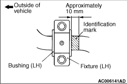
Align the stabilizer bar identification mark with the right end of the bushing (LH).
|
|
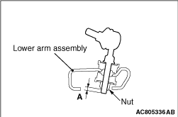
Tighten the nut until the stabilizer link thread part protruding length meets the standard
value.
Standard value (A): 5 ± 1.5 mm
|
|
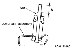
Tighten the nut until the stabilizer link thread part protruding length meets the standard
value.
Standard value (A): 22.7 ± 1.5 mm
|
 ,
Air Bag Module and Clock Spring
,
Air Bag Module and Clock Spring )
)
)
)
)
)
)
)