|
|
1.Wipe off grease from the spider assembly and the inside of the TJ case.
|
|
|
2.Always clean the spider assembly when the grease contains water or foreign material.
|
|
|
1.Wipe off grease from the shaft spline.
|
|
|
2.When reusing the TJ boot, wrap plastic tape around the shaft spline to avoid damaging
the boot.
|
|
1.
| caution |
There should be no grease adhered to the rubber part
of the dynamic damper.
|
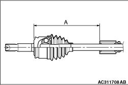
Install the dynamic damper in the position (A) shown in the figure .
A :390 + 6 mm <Except 4G1-RH>
A: 228 + 6 mm <4G1-RH>
2.For vehicles except 4G1, secure the damper bands.
|
|
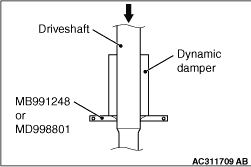
3.For vehicles with 4G1, press-fit the dynamic damper by using special tool inner shaft
remover (MB991248 or MD998801).
4.Wrap plastic tape around the shaft spline, and then install the TJ boot band (small)
and TJ boot.
|
|
|
1.
| caution |
- The driveshaft joint use special grease.
Do not mix old and new or different types of grease.
- If the spider assembly has been cleaned, take special care to apply the specified grease.
|
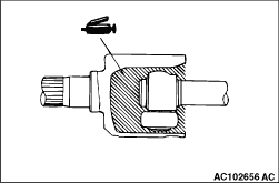
Apply the specified grease furnished in the repair kit to the spider assembly between
the spider axle and the roller.
Specified grease: Repair kit grease
|
|
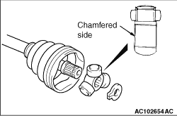
2.Install the spider assembly to the shaft from the direction of the spline chamfered side.
|
|
After applying the specified grease to the TJ case, insert the driveshaft and apply grease
one more time.
Specified grease: Repair kit grease
Amount to use : 126 ± 6 g
| note |
The grease in the repair kit should be divided in half for use, respectively, at the joint
and inside the boot.
|
|
|
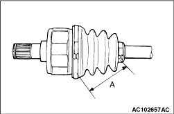
Set the TJ boot bands at the specified distance in order to adjust the amount of air inside
the TJ boot, and then tighten the TJ boot band (small), TJ boot band (large) securely.
Standard value (A): 80 ± 3 mm
<4G1>
|
|
1.Set the TJ boot bands at the specified distance in order to adjust the amount of air inside
the TJ boot, and then tighten the TJ boot band (small) securely.
Standard value (A): 80 ± 3 mm
|
|
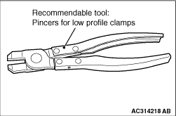
2.Use the pincers for low profile clamps <recommendable tool: Pincers for Low Profile
Clamps produced by OETIKER> to install the TJ boot band (large) by following the next steps.
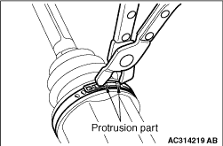
(1)
Use the pincers for low profile clamps to catch the protrusion part of the TJ boot band
(large) and tighten it firmly.
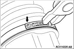
(2)
After having tightened securely the protrusion part of the TJ boot band (large), hook
the end of the TJ boot band (large) as shown in the illustration.
|
)

)
)
)
)
)
)
)
)
)