REMOVAL AND INSTALLATION


caution
  • Do not disassemble the knuckle assembly.
  • The magnetic encoder collects any metallic particle easily, because it is magnetized. Make sure that the magnetic encoder should not collect any metallic particle. Check that there is not any trouble prior to reassembling it.
  • When the front wheel hub assembly is removed and installed, make sure that the magnetic encoder does not contact with surrounding parts to avoid damage.
Post-installation Operation
  • Check the Dust Cover for cracks or damage by pushing it with your finger.


Removal steps
<<A>>
>>C<<
1.
Driveshaft nut

>>C<<
2.
Washer


3.
Front wheel speed sensor


4.
Brake hose bracket


5.
Front wheel speed sensor harness and strut assembly connection
<<B>>

6.
Caliper assembly


7.
Brake disc

>>B<<
8.
Stabilizer link bush (A) <except 4G1>

>>B<<
9.
Stabilizer link bush (B) assembly <except 4G1>

>>B<<
10.
Stabilizer link inner bush <except 4G1>

>>A<<
11.
Stabilizer link bush (A) <4G1>


12.
Flange nut <4G1>

>>A<<
13.
Stabilizer link assembly <4G1>

>>A<<
14.
Stabilizer link bush (B) <4G1>
<<C>>

15.
Self-locking nut (tie rod end connection)
<<C>>

16.
Self-locking nut (lower arm ball joint connection)
<<D>>

17.
Driveshaft


18.
Nut (hub and knuckle to strut connection)


19.
Hub knuckle assembly

REMOVAL SERVICE POINTS


<<A>> DRIVESHAFT NUT REMOVAL


caution Do not apply pressure to wheel bearing by the vehicle weight to avoid possible damage when driveshaft nut is loosened.

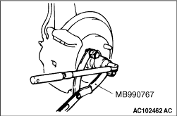
Use special tool front hub and flange yoke holder (MB990767) to fix the hub and remove the driveshaft nut.

<<B>> CALIPER ASSEMBLY REMOVAL


1.Remove the caliper assembly with brake hose.
2.Secure the removed caliper assembly with a wire or other similar material at a position where it will not interfere with the removal and installation of the hub knuckle assembly.

<<C>> SELF-LOCKING NUT (TIE ROD END CONNECTION)/SELF-LOCKING NUT (LOWER ARM BALL JOINT CONNECTION) REMOVAL


caution
  • Do not remove the nut from ball joint. Loosen it and use the special tool to avoid possible damage to ball joint threads.
  • Hang the special tool with cord to prevent it from falling.

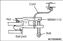
Replace the self-locking nut with a regular nut, and then install special tool steering linkage puller (MB991113) as shown in the figure.
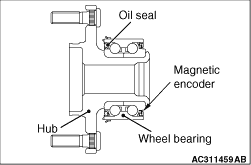
<<D>> DRIVESHAFT REMOVAL


caution
  • The magnetic encoder collects any metallic particle easily, because it is magnetized. Make sure that the magnetic encoder does not collect any metallic particle.
  • When the driveshaft is removed, make sure that it does not contact with the magnetic encoder to avoid damage.

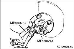
Use the following special tools to push out the driveshaft from the hub.

  • Front hub and flange yoke holder (MB990767)
  • Axle shaft puller (MB990241)

INSTALLATION SERVICE POINTS


>>A<< STABILIZER LINK BUSH (B) <4G1>/STABILIZER LINK ASSEMBLY <4G1>/STABILIZER LINK BUSH (A) <4G1> INSTALLATION


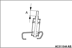
Install the stabilizer link bush (B), stabilizer link assembly and stabilizer link bush (A) as shown in the figure, and tighten the stabilizer link bush (A) so that the protruding length of the stabilizer link assembly meets its standard value (A).
Standard value (A): 5 ± 1.5 mm

>>B<< STABILIZER LINK INNER BUSH <EXCEPT 4G1>/STABILIZER LINK BUSH (B) ASSEMBLY <EXCEPT 4G1>/STABILIZER LINK BUSH (A) <EXCEPT 4G1> INSTALLATION


Install the stabilizer link bush (B) assembly, stabilizer link inner bush and stabilizer link bush (A) as shown in the figure, and tighten the stabilizer link bush (A) so that the protruding length of the stabilizer link bush (B) assembly meets its standard value (A).
Standard value (A): 22 ± 1.5 mm

>>C<< WASHER/ DRIVESHAFT NUT INSTALLATION


caution
  • The magnetic encoder collects any metallic particle easily, because it is magnetized. Make sure that the magnetic encoder should not collect any metallic particle. Check that there is not any trouble prior to reassembling it.
  • When the driveshaft is installed, make sure that it does not contact with the magnetic encoder to avoid damage.
  • Before securely tightening the driveshaft nuts, make sure there is no load on the wheel bearings. Otherwise the wheel bearings will be damaged.

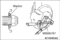
1.Be sure to install the driveshaft washer in the specified direction.
2.Using special tool front hub and flange yoke holder (MB990767), tighten the driveshaft nut to the specified torque.
Tightening torque: 236 ± 19 N·m