|
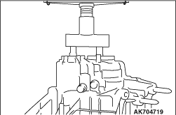
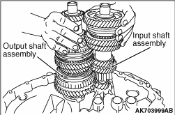
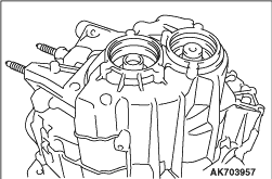
Pressing the input shaft assembly and the output shaft assembly at the same time, remove
them as shown in the illustration.
|
|
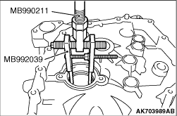
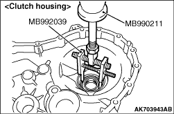
Using the special tools, support the outer ring and remove the outer ring.
- Slide hammer (MB990211)
- Slide hammer puller (MB992039)
|
|
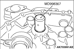
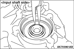
Using the special tool, Snap ring installer (MD998367), remove the input shaft seal and
input shaft roller bearing.
|
|
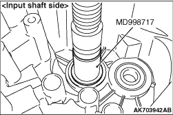
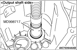
Using the special tool, Crankshaft front oil seal installer (MD998717), remove the ball
bearing.
|
|
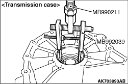
Using the special tools, support the tapered roller bearing outer race and remove the
tapered roller bearing outer race.
- Slide hammer (MB990211)
- Slide hammer puller (MB992039)
|
|
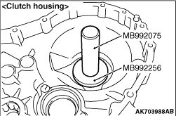
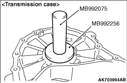
Using the special tools, install the tapered roller bearing outer race.
- Bar (MB992075)
- Bearing installer (MB992256)
|
|
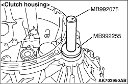
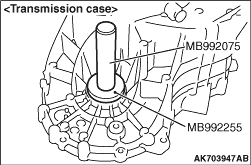
1.Using the special tools, install the seal ring.
- Bar (MB992075)
- Oil seal installer (MB992255)
2.Apply specified grease to the oil seal lip area.
Specified grease: OLISTA LONGTIME 3EP or equivalent
|
|
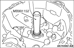
Using the special tool, Dust cover installer (MB991152), install the input shaft roller
bearing.
|
|
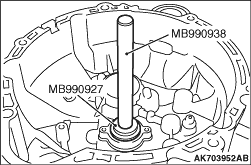
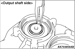
1.Using the special tools, install the input shaft seal.
- Installer bar (MB990938)
- Installer adaptor (MB990927)
2.Apply specified grease to the oil seal lip area.
Specified grease: OLISTA LONGTIME 3EP or equivalent
|
|
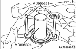
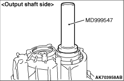
Using the special tools, install the output shaft seal and tighten the specified torque.
- Guide pin (MD999551)
- Crankshaft front oil seal installer (MD998304)
Tightening torque: 10 ± 2 N·m
|
|
1.Install the input shaft assembly and output shaft assembly as a set to the clutch housing.
|
|
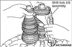
2.Install the shift fork 5/6 assembly as a set to the clutch housing.
|
|
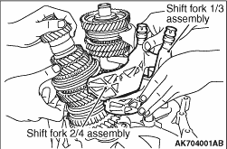
3.Slightly lifting the input shaft assembly and the output shaft assembly, install the shift
fork 2/4 assembly and the shift fork 1/3 to the clutch housing.
|
|
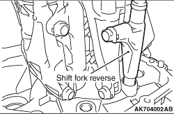
4.Install the shift fork reverse as a set to the clutch housing.
|
|
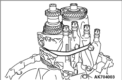
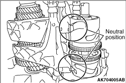
5.Using a tape, fix the input shaft assembly, output shaft assembly, shift fork 5/6, shift
fork 2/4 and shift fork 1/3 as shown in the illustration.
|
|
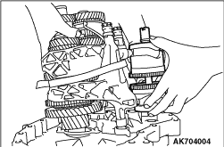
6.Slightly lifting the input shaft assembly, output shaft assembly, shift fork 5/6 assembly,
shift fork 2/4 assembly and shift fork 1/3 assembly, install the shift drum assembly.
|
|
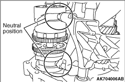
7.Make sure that each fork is in the neutral position. Install the shift drum assembly so
that the groove of the shift drum assembly and the projection of the each fork can be positioned
in the place shown in the illustration.
|
|
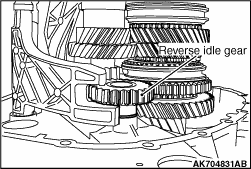
8.Install the reverse idle gear as a set to the shift fork reverse.
|
|
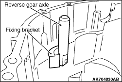
9.Temporarily install the fixing bracket, reverse gear axle and screw to the transmission
case.
|
|
10.Aligning the input shaft, output shaft, shift fork 5/6, shift fork 2/4, shift fork 1/3,
shift fork reverse, shift drum assembly and transmission case hole, install the transmission
case.
|
|
11.Tighten the screw at the specified torque.
Tightening torque: 30 ± 3 N·m
|
|
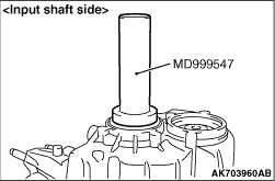
12.Using the special tool, Oil seal installer (MD999547), install the ball bearing.
|
|
13.Install the snap ring that has selected.
| note |
Try to first install the thicker snap ring to always use the thickest snap ring.
|
|
|
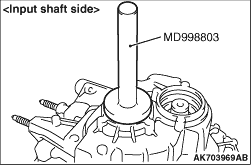
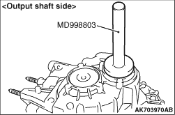
1.Using the special tool, Drive shaft oil seal installer (MD998803), install the rudder
cap.
2.Remove the temporarily installed clutch housing.
|
|
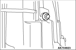
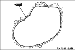
1.Apply the specified sealant to transmission case as shown.
Specified sealant: Loctite 5203 or equivalent
2.Install the clutch housing to the transmission case and tighten the specified torque.
Tightening torque: 27 ± 1 N·m
|
|
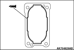
1.Apply the specified sealant to transmission case.
Specified sealant: Loctite 5203 or equivalent
2.Install the Shift actuator unit to the transmission case and tighten the specified
torque.
Tightening torque: 23 ± 2 N·m
|
)

)
)
)
)
)
)
)
)
)
)
)
)
)
)
)
)
)
)
)
)
)
)
)
)
)
)
)
)
)
)
)
)
)
)
)
)
)
)
)
)
)