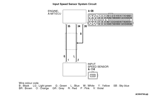
Inspection Procedure 4: Input speed sensor system malfunction
OPERATION
The input speed sensor detects the speed of the input shaft, and sends the information to the engine-A-M/T-ECU.
PROBABLE CAUSES
- Malfunction of input speed sensor
- Damaged harness wires and connectors
- Malfunction of the engine-A/T-ECU
|
|
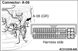
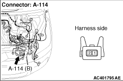
STEP 1. Connectors check: A-08 engine-A-M/T-ECU connector, A-114 input speed sensor connector.
|
|
Check for the contact with terminals.
Q.
Is the check result normal?
 Go to Step 2. Go to Step 2.
 Repair the defective connector. Repair the defective connector.
|
|
|
STEP 2. Check the wiring harness between input speed sensor connector A-114 terminal No.1, 2 and engine-A-M/T-ECU connector A-08 terminal No.35, 34, 36.
|
|
Check the wiring harness for short and open circuit.
Q.
Is the check result normal?
Go to Step 3.
Repair the wiring harness.
|
|
|
STEP 3. Input speed sensor replacement.
|
|
|
(1)Replace the input speed sensor.
|
|
|
(2)Test drive the vehicle.
|
|
|
(3)Check if a malfunction takes place again.
|
|
|
Q.
Does a malfunction take place again?
|
|
|
Go to Step 4.
|
|
|
|
|
|
The inspection is complete.
|
|
|
|
|
|
STEP 4. Engine-A-M/T-ECU replacement.
|
|
|
(1)Replace the engine-A-M/T-ECU. Then perform the variant coding and write the VIN data (Refer to GROUP 00, Precautions Before Service - How to Perform Variant Coding  ). ).
|
|
|
(2)Test drive the vehicle.
|
|
|
(3)Check if a malfunction takes place again.
|
|
|
Q.
Does a malfunction take place again?
|
|
|
Go to Step 1.
|
|
|
|
|
|
The inspection is complete.
|
|
|
|
)
)
)