Inspection Procedure 1: Malfunction of automated manual transmission control relay system

OPERATION
The engine automated manual transmission electronic control unit (Engine-A-M/T-ECU) carries out power supply via the automated manual transmission control relay.
PROBABLE CAUSES
- Malfunction of automated manual transmission control relay
- Damaged harness wires and connectors
- Malfunction of the engine-A-M/T-ECU
|
|
STEP 1. Check the automated manual transmission control relay.
|
|
|
Refer to  . .
|
|
|
Q.
Is the check result normal?
|
|
|
 Go to Step 2. Go to Step 2.
|
|
|
|
|
|
 Replace the automated manual transmission control relay. Replace the automated manual transmission control relay.
|
|
|
|
|
|
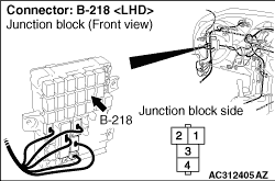
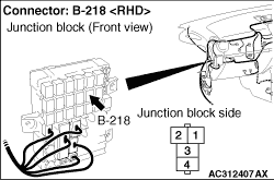
STEP 2. Measure the voltage at automated manual transmission control relay connector B-218.
|
|
Remove the automated manual transmission control relay, and measure the voltage between terminal No.1, No.3 and earth of the automated manual transmission control relay connector at the J/B side.
OK: System voltage
Q.
Is the check result normal?
Go to Step 5.
Go to Step 3.
|
|
|
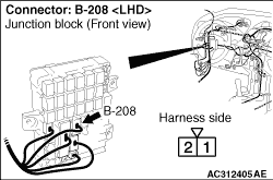
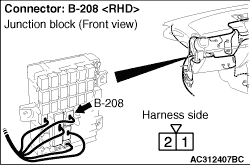
STEP 3. Connectors check: B-208 J/B connector, B-218 automated manual transmission control relay connector.
|
|
Check for the contact with terminals.
Q.
Is the check result normal?
Go to Step 4.
Repair the defective connector.
|
|
|
STEP 4. Check the wiring harness between fusible link (1) and automated manual transmission control relay connector B-218 terminal No.1, No.3.
|
|
Check the wiring harness for short and open circuit.
Q.
Is the check result normal?
Intermittent malfunction (Refer to GROUP 00 - How to Cope with Intermittent Malfunction ).
Repair the wiring harness.
|
|
|
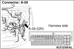
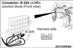
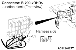
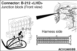
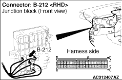
STEP 5. Connectors check: A-09 engine-A-M/T-ECU connector, B-209, B-212 J/B connector, B-218 automated manual transmission control relay connector.
|
|
Check for the contact with terminals.
Q.
Is the check result normal?
Go to Step 6.
Repair the defective connector.
|
|
|
STEP 6. Check the wiring harness between automated manual transmission control relay connector B-218 terminal No.4 and engine-A-M/T-ECU connector A-09 terminal No.71, 73, automated manual transmission control relay connector B-218 terminal No.2 and engine-A-M/T-ECU connector A-09 terminal No.109.
|
|
Check the wiring harness for short or open circuit.
Q.
Is the check result normal?
Go to Step 7.
Repair the wiring harness.
|
|
|
STEP 7. Engine-A-M/T-ECU replacement.
|
|
|
(1)Replace the engine-A-M/T-ECU. Then perform the variant coding and write the VIN data (Refer to GROUP 00, Precautions Before Service - How to Perform Variant Coding ).
|
|
|
(2)Test drive the vehicle.
|
|
|
(3)Check if a malfunction takes place again.
|
|
|
Q.
Does a malfunction take place again?
|
|
|
Go to Step 1.
|
|
|
|
|
|
The inspection is complete.
|
|
|
|
)
)
)
)
)
)
)
)
)
)