|
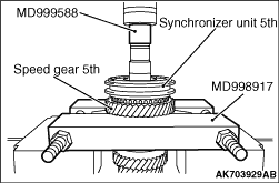
Using the special tools, support the speed gear 5th and remove the synchronizer unit 5th,
dog body 5th <F5MGA> and speed gear 5th.
- Bearing remover (MD998917)
- Valve guide installer (MD999588)
|
|
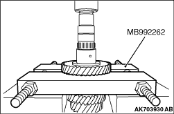
Using the special tool, Gear remover (MB992262), support the fixed gear 4th and remove
the fixed gear 4th.
|
|
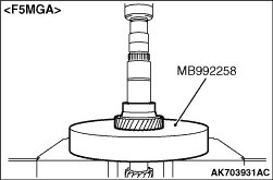
Using the special tool, Gear remover (MB992258), support the fixed gear 3rd and remove
the fixed gear 3rd. <F5MGA>
|
|
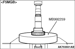
Using the special tool, Gear remover (MB992259), support the fixed gear 3rd and remove
the fixed gear 3rd. <F5MGB>
|
|
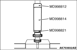
Using special tools, install the fixed gear 3rd.
- Installer cap (MD998812)
- Installer-200 (MD998814)
- Installer adapter (MD998821)
|
|
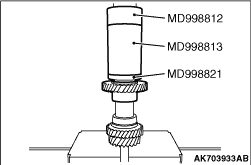
Using special tools, install the fixed gear 4th.
- Installer cap (MD998812)
- Installer-100 (MD998813)
- Installer adapter (MD998821)
|
|
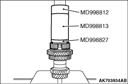
Using special tools, install the synchronizer unit 5th.
- Installer cap (MD998812)
- Installer-100 (MD998813)
- Installer adapter (MD998827)
|
)

)
)
)
)
)
)
)