|
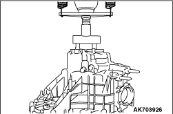
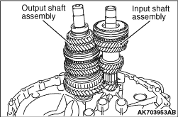
Completely pushing the input shaft assembly and the output shaft assembly at the same
time, remove them.
|
|
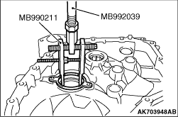
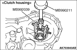
Using the special tools, support the outer ring and remove the outer ring.
- Slide hammer (MB990211)
- Slide hammer puller (MB992039)
|
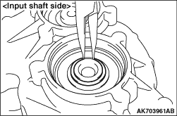
|
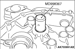
Using the special tools, Snap ring installer (MD998367), remove the input shaft seal and
input shaft roller bearing.
|
|
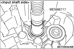
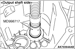
Using the special tool, Crankshaft front oil seal installer (MD998717), remove the ball
bearing.
|
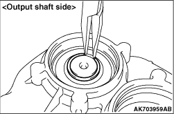
|
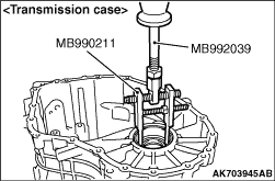
Using the special tool, support the tapered roller bearing outer race and remove the tapered
roller bearing outer race.
- Slide hammer (MB990211)
- Slide hammer puller (MB992039)
|
|
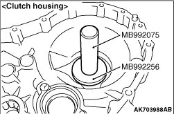
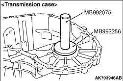
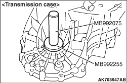
Using the special tools, install the tapered roller bearing outer race.
- Bar (MB992075)
- Bearing installer (MB992256)
|
|
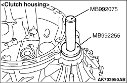
1.Using the special tools, install the oil seal.
- Bar (MB992075)
- Oil seal installer (MB992255)
2.Apply specified grease to the oil seal lip area.
Specified grease: OLISTA LONGTIME 3EP or equivalent
|
|
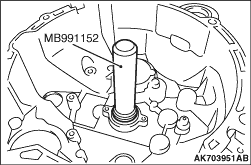
Using the special tool, Dust cover installer (MB991152), install the input shaft roller
bearing.
|
|
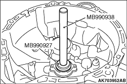
1.Using the special tools, install the input shaft seal.
- Installer bar (MB990938)
- Installer adaptor (MB990927)
2.Apply specified grease to the oil seal lip area.
Specified grease: OLISTA LONGTIME 3EP or equivalent
|
|
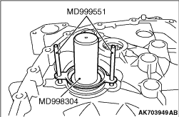
Using the special tools, install the outer ring and tighten the specified torque.
- Guide pin (MD999551)
- Crankshaft front oil seal (MD998304)
Tightening torque: 10 ± 2 N·m
|
|
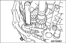
1.Install the input shaft assembly and output shaft assembly as a set to the clutch housing.
|
|
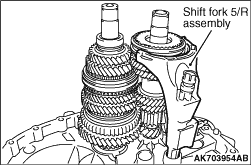
2.Install the shift fork 5/R assembly as a set to the clutch housing.
|
|
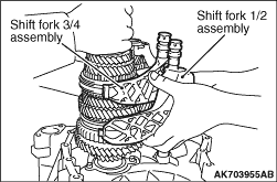
3.Slightly lifting the input shaft assembly and the output shaft assembly, install the shift
fork 1/2 assembly and the shift fork 3/4 assembly to the clutch housing.
|
|
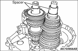
4.Install the spacer as a set to the input shaft assembly and output shaft assembly.
|
|
5.Aligning the input shaft assembly, output shaft assembly, shift fork 5/R assembly, shift
fork 1/2 assembly, shift fork 3/4 assembly, shift drum assembly and transmission case hole, install
the transmission case.
|
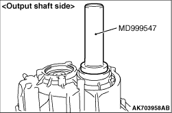
|
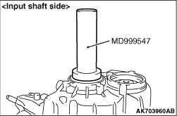
6.Using the special tool, Oil seal installer (MD999547), install the ball bearing.
|
|
7.Install the snap ring that has selected.
| note |
Try to first install the thicker snap ring to always use the thickest snap ring.
|
|
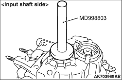
|
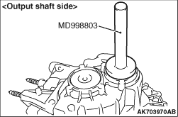
Using the special tool, Drive shaft oil seal installer (MD998803), install the rudder
cap.
|
|
|
1.Remove the temporarily installed clutch housing.
|
|
2.Attaching the fixing bracket, insert the screw to prevent it from falling out.
|
|
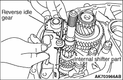
3.Install the internal shifter part, reverse idle gear and tighten the specified torque.
Tightening torque: 25 ± 2 N·m
|
|
4.Install the reverse gear axle and tighten the specified torque.
Tightening torque: 30 ± 3 N·m
|
|
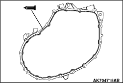
1.Completely degrease the FIPG-applied surface so that water and oil including the old
sealant cannot adhere to the surface coated with the sealant.
Never touch the degreased surface by hand.
2.Apply the specified sealant to transmission case as shown.
Specified sealant: Loctite 5203 or equivalent
3.Install the clutch housing to the transmission case and tighten the specified torque.
Tightening torque: 27 ± 1 N·m
|
|
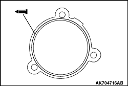
1.Completely degrease the FIPG-applied surface so that water and oil including the old
sealant cannot adhere to the surface coated with the sealant.
Never touch the degreased surface by hand.
2.Apply the specified sealant to transmission case as shown.
Specified sealant: Loctite 5203 or equivalent
3.Install the shift cover Cpl. to the transmission case and tighten the specified torque.
Tightening torque: 23 ± 2 N·m
|
 .) <Vehicles
without AS&G system>
.) <Vehicles
without AS&G system>)
)
)
)
)
)
)
)
)
)
)
)
)
)
)
)
)
)
)
)
)
)
)
)
)
)
)
)
)
)
)
)
)
)
)
)
)
)
)
)
)