|
|
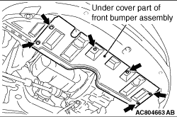
For adoption of the under cover integrated with the front bumper assembly, remove the
six front bumper clips, and lift the under cover part of front bumper assembly downward.
|
|
1.Remove the six front bumper clips shown in the figure.
|
|
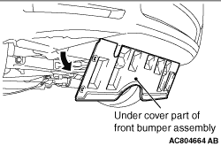
2.Lift the under cover part of front bumper assembly downward.
|
|
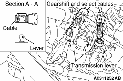
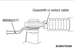
Using the clip remover (special tool: MB992277), disconnect the joint between the lever
of the transmission assembly and the gear shift cable and the joint between the lever of the transmission
assembly and the select cable.
|
|
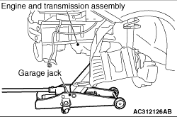
While supporting the engine and transmission assembly with a garage jack, remove the transmission
mounting insulator.
|
|
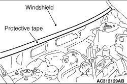
| caution |
Wrap a protective tape to avoid damage to the windshield.
|
|
|
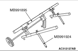
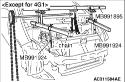
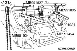
1.<Engine hanger (special tool MB991895) is used>
(1)
Remove the hook from the front side of engine hanger (special tool MB991895),
and install engine hanger attachment (special tool MB991924) instead.
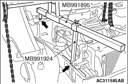
(2)
Set the hook at the rear side of engine hanger (special tool MB991895) to the front strut
mounting nut.
(3)
Set engine hanger attachment (special tool MB991924) to the front side member welded
part.
(4)
Attach the chain of engine hanger (special tool MB991895) to the engine assembly to support
the engine and transmission assembly. <Except for 4G1>
Attach the chain of engine hanger (special tool MB991895) to the hanger (special tool
MB991527) to support the engine and transmission assembly. <4G1>
|
|
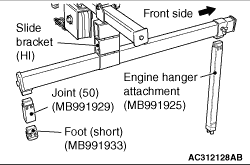
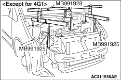
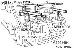
2.<Engine hanger (special tool MB991928) is used>
(1)
Assemble the engine hanger (special tool MB991928). Set following parts
to the base hanger.
- Slide bracket (HI)
- Engine hanger attachment (special tool MB991925) <Front
side>
- Foot (short) (special tool MB991933) <Rear side>
- Joint (50) (special tool MB991929) <Rear side>
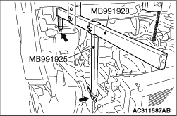
(2)
Set the foot (special tool MB991933) at the rear side of engine hanger (special tool MB991928)
to the front strut mounting nut.
(3)
Set engine hanger attachment (special tool MB991925) to the front side member welded
part.
(4)
Attach the chain of engine hanger (special tool MB991928) to the engine assembly to support
the engine and transmission assembly. <Except for 4G1>
Attach the chain of engine hanger (special tool MB991928) to the hanger (special tool
MB991527) to support the engine and transmission assembly. <4G1>
|
 .) <Vehicles with AS&G system>
)
)
)
)
)
)
)
)
)
)
)
)
)
)
)
)