
|
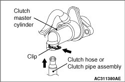
Use a screwdriver to push out the clip, and disconnect the clutch hose or clutch pipe
assembly from the clutch master cylinder.
|
|
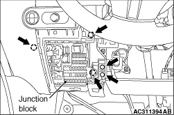
Remove the junction block by loosening the mounting screws.
|
|
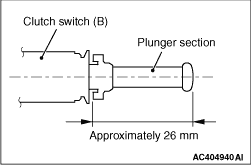
1.
| caution |
Pulling out the plunger section too frequently may damage the
automatic adjustment mechanism section of the clutch switch (B) because it is made of plastics.
If the plunger section is pulled out at least 2 or 3 times, replace the clutch switch (B).
|
Pull out the plunger section of the clutch switch (B) to the maximum length (approximately
26 mm).
| note |
The clutch switch (B) incorporates the automatic adjustment mechanism for the plunger
section.
|
|
|
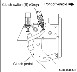
2.
| caution |
Install the clutch switch (B) (connector colour: grey) to
the position as shown.
|
Fully depress and hold the clutch pedal. Push in the clutch switch (B) to the clutch pedal
assembly bracket, and turn it clockwise in order to install.
| note |
By installing the clutch switch (B) as described above, the plunger section is adjusted
to the standard value automatically.
|
3.Connect the connector (connector colour: grey) of the clutch switch (B).
|
|
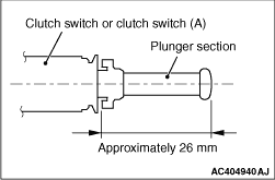
1.
| caution |
Pulling out the plunger section too frequently may damage the
automatic adjustment mechanism section of the clutch switch or clutch switch (A) because it
is made of plastics. If the plunger section is pulled out at least 2 or 3 times, replace the
clutch switch or clutch switch (A).
|
Pull out the plunger section of the clutch switch or clutch switch (A) to the maximum
length (approximately 26 mm).
| note |
The clutch switch or clutch switch (A) incorporates the automatic adjustment mechanism
for the plunger section.
|
|
|
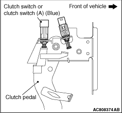
2.
| caution |
Install the clutch switch or clutch switch (A) (connector colour:
blue) to the position as shown.
|
Hold the clutch pedal to prevent it from moving, and press in the clutch switch or clutch
switch (A) to the bracket of the clutch pedal assembly. Then, turn the clutch switch or clutch switch
(A) clockwise to install it.
| note |
By installing the clutch switch or clutch switch (A) as described above, the plunger section
is adjusted to the standard value automatically.
|
3.Connect the clutch switch or clutch switch (A) connector (connector colour: blue).
|
|
Reset the clip in the original position and connect the clutch hose or clutch pipe assembly
to the clutch master cylinder.
|
 ).
).)
)
)
)
)
)
)
)
)