Code No.22 Stop
Lamp Switch System
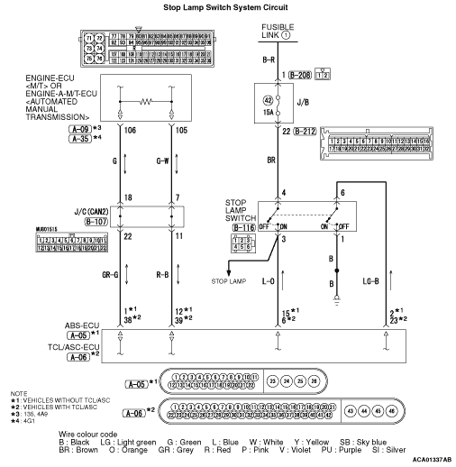
OPERATION
- For the stop lamp switch, two switches, a stop lamp switch for the stop lamp
illumination and a brake switch exclusively for the cruise control system, are incorporated
to improve the reliability.
- For the stop lamp switch and brake switch, when the brake pedal is depressed, the stop
lamp switch ON signal is transmitted from the ABS-ECU <vehicles without TCL/ASC> or TCL/ASC-ECU <vehicles
with TCL/ASC> to the engine-ECU <M/T> or engine-A-M/T-ECU <Automated
manual transmission> via CAN bus line.
DIAGNOSIS CODE SET CONDITIONS
- Open/short in stop lamp switch circuit.
- Open circuit in the brake switch circuit.
- Malfunction of CAN bus line.
PROBABLE CAUSES
- Malfunction of CAN bus system.
- Damaged harness or connector.
- Malfunction of the stop lamp switch.
- Malfunction of the ABS-ECU <vehicles without TCL/ASC>.
- Malfunction of the TCL/ASC-ECU <vehicles with TCL/ASC>.
- Malfunction of the engine-ECU <M/T>.
- Malfunction of the engine-A-M/T-ECU <Automated manual transmission>.
|
|
| caution |
- If there is any problem in the CAN bus lines,
an incorrect diagnosis code may be set. Prior to this diagnosis, diagnose the CAN bus lines.
- Before replacing the ECU, ensure that the CAN bus lines is normal.
|
|
|
|
STEP 1. Check the CAN bus system diagnosis.
|
|
|
Using M.U.T.-III, perform CAN bus diagnosis (Refer to GROUP 54C - Explanation
About The M.U.T-III Can Bus Diagnostics  ). ).
|
|
|
Q.
Is the check result satisfactory?
|
|
|
 Go to Step 2. Go to Step 2.
|
|
|
|
|
|
 Repair the CAN bus lines (Refer to GROUP 54C - Troubleshooting, Can Bus
Diagnostic Table ). Then go to Step 15. Repair the CAN bus lines (Refer to GROUP 54C - Troubleshooting, Can Bus
Diagnostic Table ). Then go to Step 15.
|
|
|
|
|
|
STEP 2. Check the data list.
|
|
|
Using M.U.T.-III, check the data list (Refer to - data
list reference table).
|
|
|
- Item 74: Stop lamp switch
|
|
|
Q.
Is the check result normal?
|
|
|
Go to Step 8.
|
|
|
|
|
|
Go to Step 3.
|
|
|
|
|
|
STEP 3. Check the ABS system <vehicles without TCL/ASC> or
TCL/ASC system <vehicles with TCL/ASC> data list.
|
|
|
Using M.U.T.-III, check the ABS system data list (Refer to GROUP 35B - Troubleshooting,
data list reference table ) <vehicles without TCL/ASC> or TCL/ASC
system data list (Refer to GROUP 35C - Troubleshooting, data list reference table ) <vehicles
with TCL/ASC>.
|
|
|
- Item 13: Stop lamp switch
|
|
|
Q.
Is the check result normal?
|
|
|
Replace the engine-ECU <M/T> or engine-A-M/T-ECU <Automated
manual transmission> (Refer to GROUP 13B - Engine-ECU, engine-A-M/T-ECU ) <135,
4A9> or (Refer to GROUP 13C - Engine-ECU ) <4G1>.
When the engine-ECU <M/T> or engine-A-M/T-ECU <Automated manual transmission> is
replaced, register the encrypted code (Refer to GROUP 54A - Ignition Switch, Encrypted
Code Registration Criteria Table ). Then go to Step 15.
|
|
|
|
|
|
Go to Step 4.
|
|
|
|
|
|
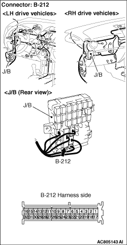
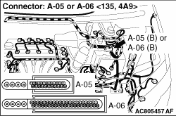
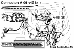
STEP 4. Connectors check: B-216 stop lamp switch connector, B-212
J/B connector, and A-05 ABS-ECU connector <vehicles without TCL/ASC> or A-06 TCL/ASC-ECU
connector <vehicles with TCL/ASC>.
|
|
Q.
Is the check result normal?
Go to Step 5.
Repair or replace the damaged connector. Then go to Step 15.
|
|
|
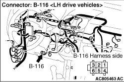
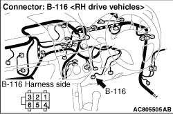
STEP 5. Check the harness wire between J/C connector B-212 terminal
No.22 and stop lamp switch connector B-116 terminal No.4, and between stop lamp switch connector
B-116 terminal No.3 and ABS-ECU connector A-05 terminal No.15 <vehicles without TCL/ASC> or
TCL/ASC-ECU connector A-06 terminal No.6 <vehicles with TCL/ASC>.
|
|
Q.
Is the check result normal?
Go to Step 6.
Repair the damaged harness wire. Then go to Step 15.
|
|
|
STEP 6. Check the stop lamp switch.
|
|
|
Refer to GROUP 35A - Brake Pedal, Inspection, Stop Lamp Switch Check .
|
|
|
Q.
Is the check result normal?
|
|
|
Go to Step 7.
|
|
|
|
|
|
Replace the stop lamp switch (Refer to GROUP 35A - Brake Pedal ).
Then go to Step 15.
|
|
|
|
|
|
STEP 7. Check the ABS system <vehicles without TCL/ASC> or
TCL/ASC system <vehicles with TCL/ASC> data list.
|
|
|
Using M.U.T.-III, check the ABS system data list (Refer to GROUP 35B - Troubleshooting,
data list reference table ) <vehicles without TCL/ASC> or TCL/ASC
system data list (Refer to GROUP 35C - Troubleshooting, data list reference table ) <vehicles
with TCL/ASC>.
|
|
|
- Item 13: Stop lamp switch
|
|
|
Q.
Is the check result normal?
|
|
|
It can be assumed that this malfunction is intermittent (Refer to GROUP 00 - How
to Use Troubleshooting/Inspection Service Points, How to Cope with Intermittent Malfunction ).
|
|
|
|
|
|
Replace the ABS-ECU (Refer to GROUP 35B - Hydraulic Unit ) <vehicles
without TCL/ASC> or TCL/ASC-ECU (Refer to GROUP 35C - Hydraulic Unit ) <vehicles with
TCL/ASC>. Then go to Step 15.
|
|
|
|
|
|
STEP 8. Check the data list.
|
|
|
Using M.U.T.-III, check the data list (Refer to - data
list reference table).
|
|
|
Q.
Is the check result normal?
|
|
|
Go to Step 14.
|
|
|
|
|
|
Go to Step 9.
|
|
|
|
|
|
STEP 9. Check the ABS system <vehicles without TCL/ASC> or
TCL/ASC system <vehicles with TCL/ASC> data list.
|
|
|
Using M.U.T.-III, check the ABS system data list (Refer to GROUP 35B - Troubleshooting,
data list reference table ) <vehicles without TCL/ASC> or TCL/ASC
system data list (Refer to GROUP 35C - Troubleshooting, data list reference table ) <vehicles
with TCL/ASC>.
|
|
|
Q.
Is the check result normal?
|
|
|
Replace the engine-ECU <M/T> or engine-A-M/T-ECU <Automated
manual transmission> (Refer to GROUP 13B - Engine-ECU, engine-A-M/T-ECU ) <135,
4A9> or (Refer to GROUP 13C - Engine-ECU ) <4G1>.
When the engine-ECU <M/T> or engine-A-M/T-ECU <Automated manual transmission> is
replaced, register the encrypted code (Refer to GROUP 54A - Ignition Switch, Encrypted
Code Registration Criteria Table ). Then go to Step 15.
|
|
|
|
|
|
Go to Step 10.
|
|
|
|
|
|
STEP 10. Connectors check: B-116 stop lamp switch connector and A-05
ABS-ECU connector <vehicles without TCL/ASC> or A-06 TCL/ASC-ECU connector <vehicles
with TCL/ASC>.
|
|
Q.
Is the check result normal?
Go to Step 11.
Repair or replace the damaged connector. Then go to Step 15.
|
|
|
STEP 11. Check the harness wire between ABS-ECU connector A-05 terminal
No.2 <vehicles without TCL/ASC> or TCL/ASC-ECU connector A-06 terminal No.23 <vehicles
with TCL/ASC> and stop lamp switch connector B-116 terminal No.6, and between stop
lamp switch connector B-116 terminal No.1 and earth.
|
|
Q.
Is the check result normal?
Go to Step 12.
Repair the damaged harness wire. Then go to Step 15.
|
|
|
STEP 12. Check the stop lamp switch.
|
|
|
Refer to GROUP 35A - Brake Pedal, Inspection, Stop Lamp Switch Check .
|
|
|
Q.
Is the check result normal?
|
|
|
Go to Step 13.
|
|
|
|
|
|
Replace the stop lamp switch (Refer to GROUP 35A - Brake Pedal ).
Then go to Step 15.
|
|
|
|
|
|
STEP 13. Check the ABS system <vehicles without TCL/ASC> or
TCL/ASC system <vehicles with TCL/ASC> data list.
|
|
|
Using M.U.T.-III, check the ABS system data list (Refer to GROUP 35B - Troubleshooting,
data list reference table ) <vehicles without TCL/ASC> or TCL/ASC
system data list (Refer to GROUP 35C - Troubleshooting, data list reference table ) <vehicles
with TCL/ASC>.
|
|
|
Q.
Is the check result normal?
|
|
|
It can be assumed that this malfunction is intermittent (Refer to GROUP 00 - How
to Use Troubleshooting/Inspection Service Points, How to Cope with Intermittent Malfunction ).
|
|
|
|
|
|
Replace the ABS-ECU (Refer to GROUP 35B - Hydraulic Unit ) <vehicles
without TCL/ASC> or TCL/ASC-ECU (Refer to GROUP 35C - Hydraulic Unit ) <vehicles with
TCL/ASC>. Then go to Step 15.
|
|
|
|
|
|
STEP 14. Read the diagnosis code.
|
|
|
(1)Disconnect the negative battery terminal, and erase the diagnosis code of the cruise
control system.
|
|
|
(2)Connect the negative battery cable.
|
|
|
(3)Turn the ignition switch to the "ON" position, and press the "ON/OFF"
switch to turn the cruise control system to ON (turn ON the cruise control indicator lamp).
|
|
|
(4)With the cruise control switches not operated, depress the brake pedal for several
seconds, and then read the diagnosis code of the cruise control system (Refer to ).
|
|
|
Q.
Is diagnosis code No.22 set?
|
|
|
Replace the engine-ECU <M/T> or engine-A-M/T-ECU <Automated
manual transmission> (Refer to GROUP 13B - Engine-ECU, engine-A-M/T-ECU ) <135,
4A9> or (Refer to GROUP 13C - Engine-ECU ) <4G1>.
When the engine-ECU <M/T> or engine-A-M/T-ECU <Automated manual transmission> is
replaced, register the encrypted code (Refer to GROUP 54A - Ignition Switch, Encrypted
Code Registration Criteria Table ). Then go to Step 15.
|
|
|
|
|
|
It can be assumed that this malfunction is intermittent (Refer to GROUP 00 - How
to Use Troubleshooting/Inspection Service Points, How to Cope with Intermittent Malfunction ).
|
|
|
|
|
|
STEP 15. Check the data list.
|
|
|
Using M.U.T.-III, check the data list (Refer to - data
list reference table).
|
|
|
- Item 74: Stop lamp switch
- Item 89: Brake switch
|
|
|
Q.
Is the check result normal?
|
|
|
Go to Step 16.
|
|
|
|
|
|
Return to Step 2.
|
|
|
|
|
|
STEP 16. Read the diagnosis code.
|
|
|
(1)Disconnect the negative battery terminal, and erase the diagnosis code of the cruise
control system.
|
|
|
(2)Connect the negative battery cable.
|
|
|
(3)Turn the ignition switch to the "ON" position, and press the "ON/OFF"
switch to turn the cruise control system to ON (turn ON the cruise control indicator lamp).
|
|
|
(4)With the cruise control switches not operated, depress the brake pedal for several
seconds, and then read the diagnosis code of the cruise control system (Refer to ).
|
|
|
Q.
Is diagnosis code No.22 set?
|
|
|
Return to Step 1.
|
|
|
|
|
|
The procedure is complete.
|
|
|
|
)
)
)
)
)
)