REMOVAL AND INSTALLATION


Pre-removal Operation
  • Air Intake Hose Removal (Refer to ).
  • Engine Coolant Draining (Refer to GROUP 14, On-vehicle Service - Engine Coolant Replacement ).
  • Engine Oil Draining (Refer to GROUP 12, On-vehicle Service - Engine Oil Replacement ).
  • Front Catalytic Converter Removal (Refer to GROUP 17, Catalytic Converter ).

Post-installation Operation
  • Front Catalytic Converter Installation (Refer to GROUP 17, Catalytic Converter ).
  • Engine Oil Refilling (Refer to GROUP 12, On-vehicle Service - Engine Oil Replacement ).
  • Engine Coolant Refilling (Refer to GROUP 14, On-vehicle Service - Engine Coolant Replacement ).
  • Air Intake Hose Installation (Refer to ).


Removal steps
<<A>>
>>D<<
1.
Oxygen sensor


2.
Turbocharger cover


3.
Pin


4.
Turbocharger waste gate actuator


5.
Turbocharger waste gate solenoid valve connector connection


6.
Harness clamp connection


7.
Turbocharger waste gate solenoid valve, vacuum hose and vacuum pipe assembly


8.
Turbocharger water return hose connection


9.
Turbocharger water return pipe


10.
Gasket
<<B>>

11.
Turbocharger oil feed tube


12.
Gasket


Removal steps


13.
Turbocharger oil return tube

>>C<<
14.
Turbocharger oil return tube gasket (oil pan side)

>>B<<
15.
Turbocharger oil return tube gasket (turbocharger assembly side)


16.
Bracket


·
Air outlet fitting (Refer to ).


17.
Turbocharger exhaust outlet fitting


18.
Gasket


19.
Bracket


20.
Turbocharger water feed hose connection

>>A<<
21.
Turbocharger assembly


22.
Gasket


23.
Turbocharger water feed pipe


24.
Gasket


25.
Vacuum hose


26.
Oil level gauge guide


27.
O-ring


28.
Nut


29.
Exhaust manifold


30.
Exhaust manifold gasket

REMOVAL SERVICE POINTS


<<A>> OXYGEN SENSOR REMOVAL


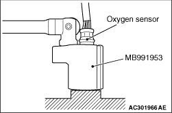
Remove the connection and clamp of oxygen sensor connector, and then use special tool oxygen sensor wrench (MB991953) to remove the oxygen sensor.

<<B>> TURBOCHARGER OIL FEED TUBE REMOVAL


caution After removing the turbocharger oil feed tube, be careful that any foreign materials does not get into the oil passages of the turbocharger.

INSTALLATION SERVICE POINTS


>>A<< TURBOCHARGER ASSEMBLY INSTALLATION


1.Clean the turbocharger oil feed tube, water feed pipe and water return pipe fitting, the inside of eye bolts, and individual pipe for clogs.
2.
caution Be careful that any foreign materials does not get into the turbocharger.
Clean or blow the air if carbon residues are stuck to the oil passages of turbocharger assembly.
3.Add new engine oil through the turbocharger oil feed tube of turbocharger assembly.

>>B<< TURBOCHAGER OIL RETURN TUBE GASKET (TURBOCHARGER ASSEMBLY SIDE) INSTALLATION


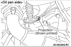
Install the gasket as its projection is in the direction shown.

>>C<< TURBOCHAGER OIL RETURN TUBE GASKET (OIL PAN SIDE) INSTALLATION


With the print area on the gasket facing to the pipe, install the gasket so that the projection is in the direction shown in the figure.

>>D<< OXYGEN SENSOR INSTALLATION


1.Tighten the oxygen sensor to the specified torque by using special tool oxygen sensor wrench (MB991953).
Tightening torque: 50 ± 10 N·m
2.Connect the oxygen sensor connector and install the connector bracket.