|
|
Using M.U.T.-III, perform CAN bus diagnosis (Refer to GROUP 54C - Explanation
About The M.U.T-III Can Bus Diagnostics  ). ).
|
|
|
Q.
Is the check result satisfactory?
|
|
|
 Repair the CAN bus lines (Refer to GROUP 54C - Troubleshooting, Can Bus
Diagnostic Table ). Then go to Step 30. Repair the CAN bus lines (Refer to GROUP 54C - Troubleshooting, Can Bus
Diagnostic Table ). Then go to Step 30.
|
|
|
|
|
|
Using M.U.T.-III, check the MPI system actuator test (Refer to GROUP 13A - Troubleshooting,
Actuator Test Reference Table ) <134, 3A9>, (Refer
to GROUP 13B - Troubleshooting, Actuator Test Reference Table ) <135,
4A9> or (Refer to GROUP 13C - Troubleshooting, Actuator Test Reference Table ) <4G1>.
|
|
|
- Item 8: Radiator fan (Hi).
- Item 9: Radiator fan (Low).
|
|
|
Q.
Is the check result normal?
|
|
|
NO <Cooling fan dose not operated> : Go to Step 3. : Go to Step 3.
|
|
|
|
|
|
NO <Cooling fan dose not operated at low speed> : Go to Step 17.
|
|
|
|
|
|
NO <Cooling fan dose not operated at high speed> : Go to Step 21.
|
|
|
|
|
|
Using M.U.T.-III, perform MPI system diagnosis code (Refer to GROUP 13A - Troubleshooting,
Diagnosis Function ) <134, 3A9>, (Refer to
GROUP 13B - Troubleshooting, Diagnosis Function ) <135,
4A9> or (Refer to GROUP 13C - Troubleshooting, Diagnosis Function ) <4G1>.
|
|
|
Q.
Is any diagnosis code set?
|
|
|
 Repair the MPI system (Refer to GROUP 13A - Troubleshooting, Inspection
Chart for Diagnosis Trouble Code ) <134, 3A9>,
(Refer to GROUP 13B - Troubleshooting, Inspection Chart for Diagnosis Trouble Code ) <135,
4A9> or (Refer to GROUP 13C - Troubleshooting, Inspection Chart for Diagnosis Trouble
Code ) <4G1>. Then go to Step 30. Repair the MPI system (Refer to GROUP 13A - Troubleshooting, Inspection
Chart for Diagnosis Trouble Code ) <134, 3A9>,
(Refer to GROUP 13B - Troubleshooting, Inspection Chart for Diagnosis Trouble Code ) <135,
4A9> or (Refer to GROUP 13C - Troubleshooting, Inspection Chart for Diagnosis Trouble
Code ) <4G1>. Then go to Step 30.
|
|
|
|
|
|
Using M.U.T.-III, perform ETACS system actuator test (Refer to GROUP 54B - Troubleshooting,
Actuator Test Table ).
|
|
|
- Item 25: Radiator fan low speed: OFF.
- Item 26: Radiator fan low speed: ON.
- Item 27: Radiator fan high speed: OFF.
- Item 28: Radiator fan high speed: ON.
|
|
|
Q.
Is the check result normal?
|
|
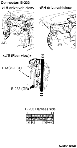
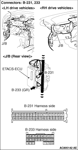
(1)Disconnect the ETACS-ECU connector B-233 and measure at the harness connector side.
(2)Turn the ignition switch to the "ON" position.
(3)Measure the voltage between terminal No.66 and earth and between terminal No.72
and earth.
OK: Battery positive voltage.
Q.
Is the check result normal?
Go to Step 12.
Go to Step 6.
|
|
Q.
Is the check result normal?
Go to Step 7.
Repair or replace the damaged connector. Then go to Step 30.
|
|
Q.
Is the check result normal?
Go to Step 8.
Repair the damaged harness wire. Then go to Step 30.
|
|
Q.
Is the check result normal?
Go to Step 9.
Repair the damaged harness wire. Then go to Step 30.
|
|
Q.
Is the check result normal?
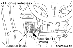
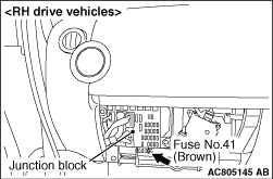
Go to Step 10.
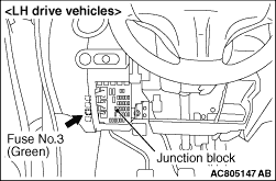
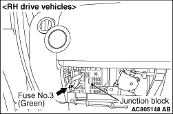
replace the damaged fuse. Then go to Step 30.
|
|
Q.
Is the check result normal?
Go to Step 11.
Repair the J/B. Then go to Step 30.
|
|
|
Q.
Is the check result normal?
|
|
|
It can be assumed that this malfunction is intermittent (Refer to GROUP 00 - How
to Use Troubleshooting/Inspection Service Points, How to Cope with Intermittent Malfunction ).
|
|
|
|
|
|
Replace the damaged relay. Then go to Step 30.
|
|
|
|
|
Q.
Is the check result normal?
Go to Step 13.
Repair or replace the damaged connector. Then go to Step 30.
|
|
Q.
Is the check result normal?
Go to Step 14.
Repair the damaged harness wire. Then go to Step 30.
|
|
Q.
Is the check result normal?
Go to Step 15.
Repair the damaged harness wire. Then go to Step 30.
|
|
Q.
Is the check result normal?
Go to Step 16.
replace the damaged fuse. Then go to Step 30.
|
|
Q.
Is the check result normal?
Go to Step 25.
Repair the J/B. Then go to Step 30.
|
|
Q.
Is the check result normal?
Go to Step 18.
Repair or replace the damaged connector. Then go to Step 30.
|
|
Q.
Is the check result normal?
Go to Step 19.
Repair the J/B. Then go to Step 30.
|
|
Q.
Is the check result normal?
Go to Step 20.
Repair the J/B. Then go to Step 30.
|
|
|
Q.
Is the check result normal?
|
|
|
Replace the damaged relay. Then go to Step 30.
|
|
|
|
|
Q.
Is the check result normal?
Go to Step 22.
Repair or replace the damaged connector. Then go to Step 30.
|
|
Q.
Is the check result normal?
Go to Step 23.
Repair the J/B. Then go to Step 30.
|
|
Q.
Is the check result normal?
Go to Step 24.
Repair the J/B. Then go to Step 30.
|
|
|
Q.
Is the check result normal?
|
|
|
Replace the damaged relay. Then go to Step 30.
|
|
|
|
|
|
Q.
Is the check result normal?
|
|
|
Replace the cooling fan motor (Refer to ) <Except
for 4G1> or (Refer to ) <4G1>. Then
go to Step 30.
|
|
|
|
|
|
Using M.U.T.-III, perform ETACS system actuator test (Refer to GROUP 54B - Troubleshooting,
Actuator Test Table ).
|
|
|
- Item 25: Radiator fan low speed: OFF.
- Item 26: Radiator fan low speed: ON.
- Item 27: Radiator fan high speed: OFF.
- Item 28: Radiator fan high speed: ON.
|
|
|
Q.
Is the check result normal?
|
|
|
Replace the ETACS-ECU (Refer to GROUP 54A - ETACS-ECU ). Then
go to Step 30.
|
|
|
|
|
|
Using M.U.T.-III, check the MPI system actuator test (Refer to GROUP 13A - Troubleshooting,
Actuator Test Reference Table ) <134, 3A9>, (Refer
to GROUP 13B - Troubleshooting, Actuator Test Reference Table ) <135,
4A9> or (Refer to GROUP 13C - Troubleshooting, Actuator Test Reference Table ) <4G1>.
|
|
|
- Item 8: Radiator fan (Hi).
- Item 9: Radiator fan (Low).
|
|
|
Q.
Is the check result normal?
|
|
|
Using M.U.T.-III, perform MPI system diagnosis code (Refer to GROUP 13A - Troubleshooting,
Diagnosis Function ) <134, 3A9>, (Refer to
GROUP 13B - Troubleshooting, Diagnosis Function ) <135,
4A9> or (Refer to GROUP 13C - Troubleshooting, Diagnosis Function ) <4G1>.
|
|
|
Q.
Is any diagnosis code set?
|
|
|
Repair the MPI system (Refer to GROUP 13A - Troubleshooting, Inspection
Chart for Diagnosis Trouble Code ) <134, 3A9>,
(Refer to GROUP 13B - Troubleshooting, Inspection Chart for Diagnosis Trouble Code ) <135,
4A9> or (Refer to GROUP 13C - Troubleshooting, Inspection Chart for Diagnosis Trouble
Code ) <4G1>. Then go to Step 30.
|
|
|
|
|
|
Q.
Is the cooling fan operate?
|
|
|
It can be assumed that this malfunction is intermittent (Refer to GROUP 00 - How
to Use Troubleshooting/Inspection Service Points, How to Cope with Intermittent Malfunction ).
|
|
|
|
|
|
Replace the engine-ECU <M/T> or engine-A-M/T-ECU <Automated manual
transmission> (Refer to GROUP 13A - Engine-ECU ) <134,
3A9>, (Refer to GROUP 13B - Engine-ECU, engine-A-M/T-ECU ) <135,
4A9> or (Refer to GROUP 13C - Engine-ECU ) <4G1>.
When the engine-ECU <M/T> or engine-A-M/T-ECU <Automated manual transmission> is
replaced, register the encrypted code (Refer to GROUP 54A - Ignition Switch, Encrypted
Code Registration Criteria Table ). Then go to Step 30 .
|
|
|
|
|
|
Q.
Does the radiator fan and condenser fan operate normal?
|
|
|
The procedure is complete.
|
|
|
|
)
)
)
)
)
)
)
)
)
)
)
)
)
)
)
)
)
)
)
)