REMOVAL AND INSTALLATION <4G1>


Pre-removal Operation
  • Engine Coolant Draining (Refer to ).
  • Thermostat Removal (Refer to ).
  • Battery and Battery Tray Removal (Refer to GROUP 54A, Battery ).

Post-installation Operation
  • Battery and Battery Tray Installation (Refer to GROUP 54A, Battery ).
  • Thermostat Installation (Refer to ).
  • Engine Coolant Supplying (Refer to ).


Removal steps
<<A>>
>>C<<
1.
Radiator upper hose connection


2.
Engine coolant temperature sensor connector


3.
Waste gate solenoid valve connector


4.
Waste gate solenoid valve, vacuum hose and pipe assembly
<<B>>

5.
Turbocharger oil feed tube


6.
Gasket

>>B<<
7.
Engine coolant temperature sensor


8.
Turbocharger water feed hose


9.
Cable band


10.
Throttle body water feed hose

>>A<<
11.
Thermostat case assembly


12.
Gasket

>>A<<
13.
O-ring


14.
Turbocharger water feed pipe


15.
Gasket


16.
Turbocharger water return hose


17.
Turbocharger water return pipe


18.
Gasket


Removal steps
<<C>>

·
Cowl top panel (Refer to GROUP 42, Loose Panel ) <COLT>.
<<C>>

·
Cowl top panel (Refer to GROUP 42, Loose Panel ) <COLT CZ3>.


19.
Control wiring harness connection


20.
Harness bracket


21.
Throttle body water return hose


22.
Cooling water line hose


23.
Cooling water inlet pipe


24.
Cooling water line hose


25.
Heater water hose connection


26.
Engine oil cooler water hose connection

>>A<<
27.
Engine oil cooler water hose and water pump inlet pipe assembly

>>A<<
28.
O-ring


29.
Engine oil cooler water feel hose


30.
Engine oil cooler water return hose


31.
Water pump inlet pipe


32.
Engine oil cooler water feel hose


33.
Engine oil cooler water return hose


·
Alternator drive belt (Refer to GROUP 11E, Crankshaft Pulley ).


34.
Engine oil pressure switch connector


35.
Cooling water inlet pipe

REMOVAL SERVICE POINTS


<<A>> RADIATOR UPPER HOSE DISCONNECTION


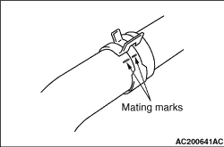
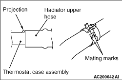
After making mating marks on the radiator upper hose and hose clamp, disconnect the radiator upper hose.

<<B>> TURBOCHARGER OIL FEED TUBE REMOVAL


caution After removing the turbocharger oil feed tube, be careful that any foreign materials does not get into the oil passages of the turbocharger.

<<C>> COWL TOP PANEL REMOVAL


caution After removing the cowl top panel, perform operation with care not to damage the windshield.

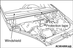
After removing the cowl top panel, attach a protection tape for the windshield on the lower area of the windshield.

INSTALLATION SERVICE POINTS


>>A<< O-RING/ENGINE OIL COOLER WATER HOSE AND WATER PUMP INLET PIPE ASSEMBLY/THERMOSTAT CASE ASSEMBLY INSTALLATION


caution Do not allow engine oil or other grease to adhere to the O-ring

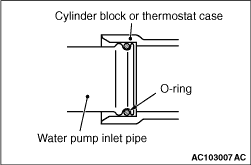
Fit the O-ring to the groove on the water inlet pipe. Apply water on the O-ring outer edge or the installation area of the water pump inlet pipe (inside the mating part), and then insert the pipe to the cylinder block or thermostat case assembly.

>>B<< ENGINE COOLANT TEMPERATURE SENSOR INSTALLATION


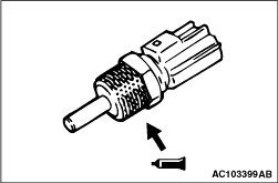
1.Apply the specified sealant to the thread of the engine coolant temperature sensor.
Specified Sealant: LOCTITE 262 or equivalent
note Install the engine coolant temperature sensor immediately after the application of sealant.
2.
caution After the installation, until a sufficient period of time (one hour or more) elapses, do not apply the engine oil or water to the sealant application area or start the engine.
Tighten the engine coolant temperature sensor to the specified torque.
Tightening torque: 30 ± 9 N·m

>>C<< RADIATOR UPPER HOSE CONNECTION


1.Insert radiator upper hose as far as the projection of the thermostat case assembly.
2.Align the mating marks on the radiator upper hose and hose clamp, and then connect the radiator upper hose.