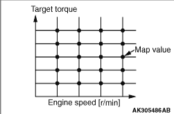
MIVEC (Mitsubishi Innovative Valve timing Electronic Control system) <135 engine>


The MIVEC continuously and variably controls the intake valve timing (while the valve opening duration remains unchanged).
MIVEC can control the valve timing optimally in accordance with the operating conditions of the engine, thus improving its idling stability and increasing the power output and torque in all operating ranges.

BASIC OPERATION


Timing Advance


Timing Retard


Holding


OPERATION UNDER VARIOUS DRIVING CONDITIONS


The system advances or retards the timing in accordance with the driving conditions in order to improve fuel economy and power output.
Conceptual Diagram of Operation

Driving condition
Valve timing
Operation
Effect
Idling


The valve overlap is decreased to minimize the amount of exhaust gas that flows back into the intake port.
Stabilizes idle speed
Low- to medium-speed


The timing to close the intake valve is accelerated to minimize the amount of intake air that flows back into the intake port. This improves volumetric efficiency and increases low- to medium-speed torque.
Improves low- to medium-speed torque
High-speed


The timing to close the intake valve is retarded in accordance with the engine speed, thus controlling the valve timing to suit the inertial force of the intake air and improving volumetric efficiency.
Improves output

OIL CONTROL VALVE CONTROL


System Configuration Diagram


PHASE ANGLE CONTROL


The table below gives an example of the relationship between the valve opening/closing timing and the phase angles.

<135930 engine>
Phase angle (camshaft)
Valve open
Valve close
75° (most retarded)
ATDC 9°
ABDC 53°
50° (most advanced)
BTDC 41°
ABDC 3°
50° - 75° (in between)
BTDC 41° - ATDC 9°
ABDC 3° - ABDC 53°

<135950 engine>
Phase angle (camshaft)
Valve open
Valve close
75° (most retarded)
ATDC 9°
ABDC 61°
50° (most advanced)
BTDC 41°
ABDC 11°
50° - 75° (in between)
BTDC 41° - ATDC 9°
ABDC 11° - ABDC 61°
note Stoppers are provided at the most advanced and most retarded positions.

CALCULATING THE ACTUAL PHASE ANGLE


The actual phase angle is calculated by using the crank angle sensor output signals and the camshaft position sensor output signals.


OIL CONTROL VALVE ACTUATION


Target Phase Angle
    The target phase angle is read by way of the map value that is preset for the respective engine speed and target torque.
Feedback Correction
    When the deviation between the target phase angle and the actual phase angle is positive (the valve opens earlier than the target) the actuation duty cycle decreases gradually in order to match the actual phase angle to the target phase angle.
    On the other hand, if the deviation between the target phase angle and the actual phase angle is negative (the valve opens later than the target), the actuation duty cycle increases gradually in order to match the actual phase angle to the target phase angle.
    When the deviation between the target phase angle and the actual phase angle is practically zero, the oil control valve (after a learning correction) is actuated with the neutral duty cycle.
Actual Phase Angle Correction
    The actual phase angle when the oil control valve is OFF is stored in learning memory as the minimum phase angle.
    When the oil control valve is OFF, the actual phase angle is compensated using the deviation between the phase angle 75° and the maximum phase angle (the sensor error), because the intake camshaft sprocket is accurately designed with phase angle 75°.

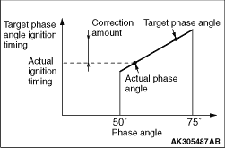
Actual Phase Angle Correction for Ignition Timing
    Due to mechanical constraints, the actual phase angle is late in responding to the changes in the target phase angle. Therefore, until the actual phase angle catches up with the target phase angle, the ignition timing is corrected in accordance with the deviation between the target phase angle and the actual phase angle.