IGNITION TIMING AND DISTRIBUTION CONTROL


An ignition timing that suits the operating condition of the engine is preset, and optimal ignition timing is determined by adding corrections that have been preset in accordance with conditions such as the engine coolant temperature or the battery voltage. Then, the engine-ECU or engine-A-M/T-ECU controls the ignition timing by applying the primary current intermittently to a power transistor.
The firing order is as follows: cylinder 1-3-2 <134 engine>, cylinder 1-3-4-2 <135 engine>
System Configuration Diagram

Control Block Diagram


IGNITION DISTRIBUTION CONTROL


The cylinders to be ignited are determined in accordance with the crank angle sensor and camshaft position sensor signals. The ignition timing is calculated in accordance with the crank angle sensor signals. Then, the engine-ECU or engine-A-M/T-ECU sends a signal for cutting off the primary current to the ignition coil to the power transistor of the respective cylinders.
<134 engine>

The cylinder is identified by the signal patterns from the crank angle sensor and the camshaft position sensor.

  1. When a chipped tooth is detected through crank angle sensor signal, check whether the signals of the camshaft position sensor exist or not within the range of (a). If the signals exist, identify the cylinders. Unless the signals exist, do not identify the cylinder.
  2. The cylinders are identified by how many signals come from the camshaft position sensor within the range of (b) and by how many teeth exist through the crank angle sensor signals
Number of chipped teeth through crank angle sensor signal
2
1
1
Any
Number of signals from camshaft position sensor
Range of (a)
Exists
Exists
Exists
None
Range of (b)
1
2
1
-
Cylinder identified
No. 1 cylinder 75° BTDC
No. 3 cylinder 75° BTDC
No. 2 cylinder 75° BTDC
-
Once the cylinder identification is completed, ignition occurs in accordance with the cylinder that has been identified, in the following firing order: 1-3-2.
<135 engine>

The cylinder is identified by the signal patterns from the crank angle sensor and the camshaft position sensor.
Number of chipped teeth through crank angle sensor signal
1
2
1
2
camshaft position sensor signal
135° BTDC
Exists
Exists
Exists
Exists
100° BTDC
None
Exists
Exists
None
Cylinder identified
No. 1 cylinder 75° BTDC
No. 3 cylinder 75° BTDC
No. 4 cylinder 75° BTDC
No. 2 cylinder 75° BTDC
Once the cylinder identification is completed, ignition occurs in accordance with the cylinder that has been identified, in the following firing order: 1-3-4-2.

IGNITION TIMING CONTROL


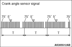
During normal driving, a forecast cycle of the crank angle sensor signals is calculated in accordance with the 75° BTDC signals of the crank angle sensor. Then, the ignition timing is calculated in accordance with the forecast calculation, and primary current cutoff signals are sent to the power transistor (for ignition).
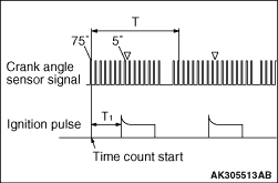
During starting and checking the ignition timing, ignition is synchronized to the 5° BTDC signal of the crank angle sensor.

CYCLE FORECAST


The cycle is measured by using the 75° BTDC signal of the crank angle sensor as a reference. The subsequent cycle is forecast in accordance with the cycle (T) that has been measured currently. The subsequent cycle that has been forecasted will be used for calculating the ignition timing.

IGNITION TIMING


The length of time (t) required for the crankshaft to turn 1° is obtained from cycle (T), as follows:
t = T/240*1 or 180*2

    *1: for 134 engine
    *2: for 135 engine
After t has been obtained, the ignition timing (T1) is calculated by using 75° BTDC as a reference. After the T1 time has elapsed from the time the 75° BTDC signal has been input, the engine-ECU or engine-A-M/T-ECU sends a primary current cutoff signal to the power transistor.
T1 = t × (75 - a)

    a: Ignition timing advance (crank angle) calculated by the engine-ECU or engine-A-M/T-ECU

IGNITION TIMING ADVANCE ANGLE CONTROL


An ignition timing advance angle that is optimal for the intake manifold vacuum (engine load) and the engine speed is stored in memory at the engine-ECU or engine-A-M/T-ECU. This timing advance angle is further corrected by the signals that are input by the sensors. However, the ignition timing is fixed to a predetermined angle when the engine is being started or when the ignition timing is being checked.
Ignition Timing Advance Angle Control Block Diagram


NORMAL DRIVING


Basic Ignition Timing Advance Angle
Engine Coolant Temperature Correction
Intake Air Temperature Correction

STARTING


When the engine is starting (cranking), ignition takes place at a fixed timing of 5° BTDC, in sync with the crank angle sensor signal.

IGNITION TIMING CHECKING CONTROL


During the reference ignition timing set mode by the actuator test function of the M.U.T.-III, ignition takes place at a fixed timing of 5° BTDC, in sync with the crank angle sensor signal.

KNOCK CONTROL


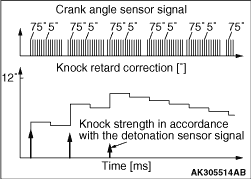
If the engine knocks while operating under high loads, the detonation sensor detects the knocking and optimally controls the ignition timing, thus minimizing knocking and protecting the engine.
Knock Control Block Diagram (Overview)


Knock Timing Retard Correction
    Each time a 75° BTDC signal is input by the crank angle sensor, the engine-ECU or engine-A-M/T-ECU determines the knock strength and adds an amount of timing retard in proportion to the knock strength to the knock timing retard correction. Thus, the engine-ECU or engine-A-M/T-ECU increases the knock timing retard correction by retarding the ignition timing until the knocking is eliminated.
    After the engine no longer knocks, the ignition timing is advanced gradually at predetermined time intervals in order to restore the normal ignition timing advance.
    If there is an open or short circuit in the wiring harness for the detonation sensor, the engine operates at an ignition timing that corresponds to the standard petrol, in order to prevent the engine from knocking.

CURRENT DURATION CONTROL


Current Duration Control Block Diagram


NORMAL DRIVING


Basic Current Duration
Closed Circuit Rate Clip

STARTING


When the engine is starting (cranking), current is applied to the ignition coil in sync with the crank angle sensor signals.