FUEL INJECTION CONTROL


This system controls the fuel injection volume in order to achieve an optimal air-fuel ratio to suit the constantly changing operating conditions of the engine. Basically, the fuel injection volume is determined by the injection frequency in accordance with the engine speed and the injection duration in accordance with the intake air volume. Fuel is injected into individual cylinders at the rate of one injection for every two revolutions of the engine. The injection duration (injector actuation duration) is the sum of the basic actuation duration (which is determined by the intake air volume of the cylinders) and a correction duration (which is determined by the conditions such as the intake air temperature and the engine coolant temperature).
System Configuration Diagram

Control Block Diagram


INJECTOR ACTUATION (FUEL INJECTION) TIMING


The multi-point injection (MPI) system controls the actuation timing of the injectors in accordance with the driving conditions, as follows:

FUEL INJECTION DURING CRANKING


<134 engine>

<135 engine>

While the engine is cranking, fuel is injected in sync with the crank angle sensor signals.

FUEL INJECTION DURING NORMAL DRIVING


<134 engine>

<135 engine>

The injectors are actuated during the exhaust stroke of the cylinders. The cylinders are identified through a comparison of the pulse signals output by the crank angle sensor and the camshaft position sensor. Using this identification as a reference, fuel is injected sequentially to the cylinders (134 engine: 1-3-2; 135 engine: 1-3-4-2). The injection of fuel to the cylinders, which is timed optimally in accordance with the crank angle sensor signals, occurs once for every two revolutions of the crankshaft.

FUEL ENRICHMENT INJECTION DURING ACCELERATION


<134 engine>

<135 engine>

During acceleration, a volume of fuel is injected in accordance with the extent of acceleration, in addition to the fuel that is injected in sync with the crank angle sensor signals.

FUEL INJECTION VOLUME (INJECTOR ACTUATION DURATION) CONTROL


The diagram below describes the calculation flow of the injector actuation duration.
The basic actuation duration is determined by the manifold absolute pressure (MAP) sensor signals (intake manifold pressure signals) and the crank angle sensor signals (engine speed signals). An actuation duration correction based on the signals provided by various signals is added to the basic actuation duration in order to obtain an optimal injector actuation duration (fuel injection volume) that suits the driving conditions.
Fuel Injection Volume Control Block Diagram


BASIC INJECTOR ACTUATION DURATION


Fuel is injected into each cylinder at a rate of once every cycle. The fuel injection volume (injector actuation duration) that attains the stoichiometric air-fuel ratio in proportion to the intake air volume per cylinder per cycle is called the basic actuation duration. Because the fuel injection volume fluctuates due to the pressure difference (injection fuel pressure) between the manifold pressure and the fuel pressure (constant), the basic actuation duration is obtained by adding injection fuel pressure correction to the fuel injection volume that attains the stoichiometric air-fuel ratio.


The engine-ECU or engine-A-M/T-ECU calculates the intake air volume per cylinder per cycle in accordance with the manifold absolute pressure (MAP) sensor signals and the crank angle sensor signals. At the time the engine is started, the map value that is determined by the engine coolant temperature signals is rendered as the basic actuation duration.
Calculating the Intake Air Volume Per Cylinder Per Cycle


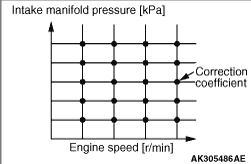
However, the volume of air that is actually drawn into the engine will be influenced by factors such as the valve train or the intake air pulsations. Therefore, the actual air volume will be less than the calculated air volume at a given rate, in accordance with the engine speed and the intake manifold pressure.
For this reason, the calculated intake air volume is corrected by a map value, which has been predetermined for the respective engine speed and intake manifold pressure, so that it will be equal to the actual intake air volume.
Dividing the intake air volume after the correction into four parts will yield the actual intake air volume per cylinder per cycle.

INJECTOR ACTUATION DURATION CORRECTION


An oxygen sensor feedback correction or an air-fuel ratio correction is made after the basic injector actuation duration has been determined.


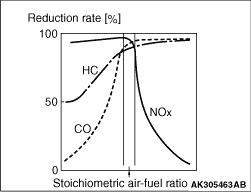
  • Oxygen Sensor Feedback Correction
    During normal driving, the injector actuation duration is corrected in accordance with the oxygen sensor signals in order to attain the stoichiometric air-fuel ratio in which the reduction rate of the three-way catalyst is at the optimum level.
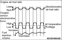
  • Operation
      If the actual air-fuel ratio is richer than the stoichiometric air-fuel ratio, the oxygen concentration in the exhaust gases is low. Therefore, the oxygen sensor will input a high electromotive force (rich signal) into the engine-ECU or engine-A-M/T-ECU.
      When the engine-ECU or engine-A-M/T-ECU receives a rich signal, it decreases the feedback correction coefficient in order to decrease the fuel injection volume.
      Conversely, if the actual air-fuel ratio is leaner than the stoichiometric air-fuel ratio, the oxygen concentration in the exhaust gases is high. Therefore, the oxygen sensor will input a low electromotive force (lean signal) into the engine-ECU or engine-A-M/T-ECU.
      When the engine-ECU or engine-A-M/T-ECU receives a lean signal, it increases the feedback correction coefficient in order to increase the fuel injection volume.
      The system continuously effects feedback control in this manner in order to attain the correct stoichiometric air-fuel ratio.
      To ensure the proper driveability, this control will not be effected under the conditions given below (instead, it will make an air-fuel ratio correction).

      • Starting the engine
      • Sudden acceleration or deceleration
      • High-speed operation
      • Cold engine
      • High-load operation
      • Oxygen sensor inactive
  • Oxygen Sensor Deterioration Correction
    The performance of the oxygen sensor (front), which is installed upstream of the catalytic converter, deteriorates gradually with the prolonged use of the vehicle or the increase in its mileage.
    However, the performance of the oxygen sensor (rear), which is installed downstream of the catalytic converter, hardly deteriorates because the catalytic converter cleans the exhaust gases.
    The engine-ECU or engine-A-M/T-ECU effects feedback control by using the signals that are output by the oxygen sensor (front). Also, it uses the signals that are output by the oxygen sensor (rear) in order to correct the signals that are output by the oxygen sensor (front). Therefore, the air-fuel ratio can be controlled accurately even if the performance of the oxygen sensor (front) deteriorates.
  • Air-Fuel Ratio Correction
    Except when oxygen sensor feedback control is being effected, the intake air volume is corrected through a map value, which has been predetermined for the respective engine speed and intake manifold pressure.
    Then, the corrections indicated below are made in order to determine an optimal fuel injection volume.
  • Atmospheric Pressure Correction
    As the intake air density changes with the changes in the atmospheric pressure, the deviation in the air-fuel ratio, which is caused by this difference in density, must be corrected. The atmospheric pressure is estimated based on the voltage that is output by the manifold absolute pressure (MAP) sensor with the ignition switch turned ON (engine stopped) and a wide-open-throttle.
  • Engine Coolant Temperature Correction
    To ensure the proper drivability when the engine coolant temperature is low, a correction is made to increase the fuel injection volume.
  • Intake Air Temperature Correction
    As the intake air density changes with the changes in the intake air temperature, a correction is made in the deviation in the air-fuel ratio, which is caused by this difference in temperature.
  • Acceleration and Deceleration Correction
    A correction is made in accordance with the changes in the intake air volume in order to ensure the proper driveability during sudden acceleration or deceleration.
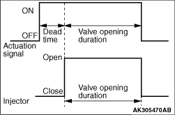
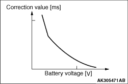
  • Dead Time Correction
    The injector valve opens in accordance with the actuation signals provided by the engine-ECU or engine-A-M/T-ECU. This action is delayed as the battery voltage decreases, making the injector spray a lower volume of fuel than the target fuel injection volume. For this reason, a correction is made in accordance with the battery voltage.

DECELERATION FUEL LIMIT CONTROL


When the vehicle is decelerating, such as when driving downhill, the control limits the delivery of fuel in order to protect the catalyst from overheating and improve fuel economy.

OVERRUN FUEL CUTOFF CONTROL


When the engine operates above the predetermined speed of 6,800 r/min, this control cuts off fuel to protect the engine by preventing it from overrunning.

FLEXIBLE FUEL VEHICLE (FFV) SYSTEM <FFV>


The fuel that is blends of petrol and ethanol prevails. To take action against the fuel that is blends of petrol and ethanol, the engine-ECU detects the ethanol concentration, using the signal output by the oxygen sensor (front). The ethanol concentration which the engine-ECU can detect is from the petrol (0% ethanol by volume) to the ethanol [E85 (85% ethanol by volume)]. Thus, the engine-ECU controls the amount of fuel injection to obtain the appropriate air-fuel ratio according to the ethanol concentration.


Control of estimated ethanol concentration


The theoretical air-fuel ratio of ethanol (E85) is approximately 9.9. This is different from the theoretical air fuel ratio for petrol (approximately 14.7). Hence, the amount of fuel injection must be reduced or increased according to the change in the concentration when the ethanol concentration changes in the fuel tank. Every time when starting the engine or supplying the fuel, the engine-ECU estimates the ethanol concentration during the specified period. Moreover, the signal of carrying out the forced learning of the estimated ethanol concentration can be sent to the engine-ECU, using the MUT-III. This allows the engine-ECU to forcibly estimate the ethanol concentration. The engine-ECU estimates the ethanol concentration through the output signal of the oxygen sensor (front) during the mode of estimating the ethanol concentration. If the change in the ethanol concentration is more than the specified value, the engine-ECU updates the learning of the estimated ethanol concentration. This allows the engine-ECU to control the amount of fuel injection in order to obtain the optimum air-fuel ratio according to the amount of change in the ethanol concentration.