|
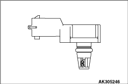
The manifold absolute pressure (MAP) sensor, which is mounted on the intake manifold,
inputs a voltage that corresponds to the intake manifold pressure into the engine-ECU or engine-A-M/T-ECU.
The engine-ECU or engine-A-M/T-ECU calculates and determines the basic fuel injection
duration based on this output voltage and the engine speed.
Furthermore, it converts the voltage that is output by the sensor when ignition switch
is ON (with the engine stopped) and the throttle fully open into atmospheric pressure and uses
this value for various types of calculations.
|
|
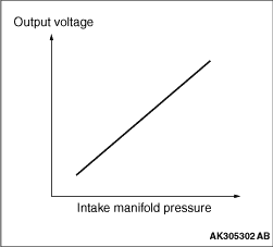
The diagram describes the characteristics of this sensor.
|
|
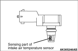
The intake air temperature sensor, which is built into the manifold absolute pressure
(MAP) sensor, detects the intake air temperature through the changes in the resistance of its thermistor.
The engine-ECU or engine-A-M/T-ECU detects the intake air temperature based on this output
voltage and corrects the fuel injection volume to suit the intake air temperature.
|
|
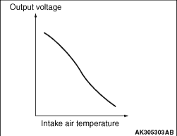
The diagram describes the characteristics of this sensor.
|
|
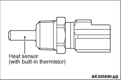
The engine coolant temperature sensor, which is mounted on the cylinder head, detects
the temperature of the engine coolant through the changes in the resistance of its thermistor.
The engine-ECU or engine-A-M/T-ECU appropriately controls the fuel injection volume, idle
speed, and the ignition timing when the engine is cold, in accordance with this output voltage.
|

|
The diagram describes the characteristics of this sensor.
|
|
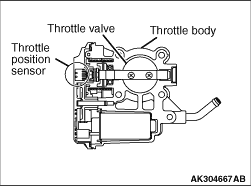
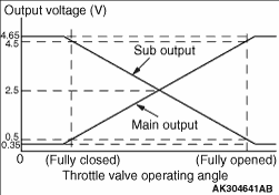
The throttle position sensor, which is built into the throttle body, inputs a voltage
that corresponds to the rotational angle of the throttle shaft into the engine-ECU or engine-A-M/T-ECU.
The TPS has two output systems: TPS (main) and TPS (sub). When the throttle valve rotates,
the output voltages of the TPS (main) and TPS (sub) change, enabling the engine-ECU or engine-A-M/T-ECU
to detect the extent of the opening of the throttle valve.
Based on these output voltages, the engine-ECU or engine-A-M/T-ECU controls the throttle
valve control servo in order to attain the target opening at the throttle valve.
Furthermore, the engine-ECU or engine-A-M/T-ECU monitors the TPS for malfunctions by comparing
the voltages that are output by the TPS (main) and the TPS (sub).
Based on this signal, the engine-ECU or engine-A-M/T-ECU effects feedback control on the
throttle valve control servo. The throttle position sensor is a non-contact type that uses a
Hall IC to ensure reliability.
|
|
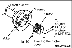
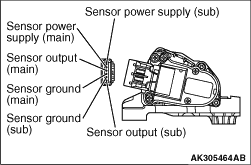
The throttle position sensor consists of a permanent magnet that is mounted on the throttle
shaft, a Hall IC that outputs a voltage in accordance with the magnetic flux density, and a stator
that effectively guides the magnetic flux from the permanent magnet to the Hall IC.
|
|
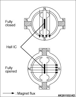
When the throttle valve is fully closed, the density of the magnetic flux that passes
through the Hall IC is the lowest.
When the throttle valve is fully open, the density of the magnetic flux that passes through
the Hall IC is the highest.
|
|
The diagram describes the relationship between the extent of the opening of the throttle
and the output voltage.
|
|
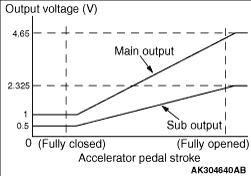
The accelerator position sensor, which is a variable resistor that rotates in unison with
the movement of the accelerator pedal, detects the amount of pedal effort applied to the accelerator.
The APS is mounted on the accelerator pedal arm.
The APS has two output systems: APS (main) and APS (sub). The voltages output by the APS
(main) and the APS (sub) (which change in accordance with the amount of pedal effort applied
to the accelerator) enable the engine-ECU or engine-A-M/T-ECU to detect the amount of pedal
effort applied to the accelerator.
The engine-ECU or engine-A-M/T-ECU uses the output voltage of the APS (main) for calculating
the target throttle opening and fuel injection volume.
Furthermore, the engine-ECU or engine-A-M/T-ECU monitors the APS for malfunctions by comparing
the voltages output by the APS (main) and the APS (sub).
|
|
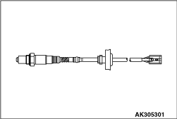
The oxygen sensors are mounted in upstream and downstream of the catalytic converter.
Each sensor has a built-in heater for accelerating the activation of the sensor. This feature
enables the system to effect air-fuel ratio feedback control in a short time.
|
|
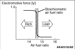
This sensor utilizes the principle of the solid-electrolyte oxygen concentration cell,
which has a characteristic of suddenly changing its output voltage in the vicinity of the stoichiometric air-fuel
ratio.
This characteristic is utilized by the sensor to detect the oxygen concentration in the
exhaust gases, and feed back this data to the engine-ECU or engine-A-M/T-ECU. Thus, the engine-ECU or
engine-A-M/T-ECU determines whether the air-fuel ratio is richer or leaner than the stoichiometric
air-fuel ratio.
|
|
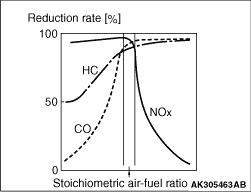
Thus, the system effects feedback control in order to achieve the stoichiometric air-fuel
ratio in which the reduction rate of the three-way catalyst is at the optimal level.
|
|
The crank angle sensor detects the crank angle for each cylinder.
Based on the pulse signals that are output by the crank angle sensor, the engine-ECU or
engine-A-M/T-ECU identifies the cylinders, and calculates the engine speed and the air intake volume
per stroke. Thus, the engine-ECU or engine-A-M/T-ECU calculates the fuel injection volume, fuel
injection timing, and the ignition timing.
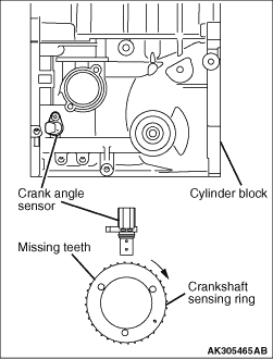
The crank angle sensor consists of a crankshaft sensing ring that is mounted on the crankshaft
and a crank angle sensor (sensing unit) that is mounted on the cylinder block.
The sensing ring contains vanes (134 engine: 32 vanes, 135 engine: 33 vanes), and the
sensing unit portion of the crank angle sensor has a built-in magnetic resistance element and
a magnet to detect the travel of the vanes.
|
|
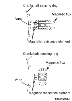
As the sensing ring rotates, the vanes of the sensing ring pass in front of the crank
angle sensor (sensing unit).
When a vane is in front of the sensing unit, the magnetic flux that is output by the magnet
passes through the magnetic resistance element, thus increasing the resistance.
When there is no vane in front of the sensing unit, the magnetic flux that is output by
the magnet does not pass through the magnetic resistance element, thus decreasing the resistance.
The crank angle sensor outputs the changes in resistance in the magnetic resistance element
by converting them into 5 V pulse signals.
|
|
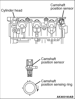
The camshaft position sensor is used for identifying the cylinders jointly with the crank
angle sensor.
The camshaft position sensor consists of a sensing ring that is mounted on the rear end
of the intake camshaft, and a camshaft position sensor (sensing unit) that is mounted on the rear
end of the cylinder head.
The engine-ECU or engine-A-M/T-ECU identifies the cylinders by comparing the pulse signals
output by the crank angle sensor and the pulse signals output by the camshaft position sensor.
As a result, the engine-ECU or engine-A-M/T-ECU determines the fuel injection cylinder and ignition
cylinder.
The construction of the camshaft position sensor is basically the same as that of the
crank angle sensor.
|
|
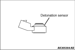
The detonation sensor is mounted at a position in which it can accurately detect the knocking
that occurs in the cylinders. It detects the vibration of the cylinder block caused by knocking and
outputs a voltage that is proportionate to the extent of the knocking.
The vibration frequency of the cylinder block caused by knocking is predetermined for
each engine. The engine-ECU or engine-A-M/T-ECU passes the vibration frequency through a frequency
filter in order to detect only the knocking, and retards the ignition timing in accordance with
the extent of knocking.
|
|
|
This signal detects the ON/OFF condition of the ignition switch (IG1).
|
|
|
When this signal is input, the engine-ECU or engine-A-M/T-ECU energizes the control relay
coil and supplies power to the injectors, manifold absolute pressure sensor, throttle valve control
servo, and the crank angle sensor.
|
|
|
This signal detects that the engine is cranking.
|
|
|
Based on this signal, the engine-ECU or engine-A-M/T-ECU controls the fuel injection,
throttle valve control servo, and the ignition timing to suit the starting conditions.
|
|
|
After turning on the ignition switch, the current is input by the engine-ECU or engine-A-M/T-ECU
to the alternator L terminal. This allows the voltage regulator to be on and the field coil
to be excited. When the alternator rotates in this situation, the voltage is excited in the
stator coil and the current is output from B-terminal through the commutation diode. Also the generated
voltage is input to the voltage regulator through the commutation diode. After the electric
generation begins, the current is supplied to the field coil from this circuit. In addition, the
generated voltage is output from the alternator L terminal to the engine-ECU or engine-A-M/T-ECU.
This allows the engine-ECU or engine-A-M/T-ECU to detect that the electric generation begins.
The engine-ECU or engine-A-M/T-ECU outputs the ON signal to the combination meter through the CAN
and then turns off the charge lamp.
|
|
The neutral position sensor is installed to the transmission case around the shift cover
Cpl. The neutral position sensor outputs the duty signal to the engine-ECU, corresponding to
the shift lever position. Based on this, the engine-ECU identifies the shift lever being in
the neutral position.
|
|
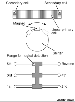
The linear primary coil is in the neutral position sensor. The permanent magnet is on
the linear primary coil. The permanent magnet is installed to the shift cover Cpl. If the shift
lever is in the neutral position, the permanent magnet is in the center of the linear primary
coil. When the shift lever is operated, the permanent magnet on the linear primary coil moves
right and left. At the same time, the voltage of the linear primary coil changes.The change
in the voltage is detected by the secondary coils at the both ends of the linear primary coil.The detected
signal is calculated by the neutral position sensor. The duty signal is sent to the engine-ECU,
corresponding to the neutral position. The relation between the neutral position and the output
duty signal is as follows:
|

|
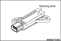
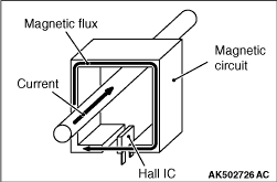
The battery current sensor is installed to the battery negative cable. Based on the magnetic
flux going through the hall element, the battery current sensor detects the amount and the direction
of electrical current going through the battery terminal. The battery current sensor converts
them into the voltage to output them to the engine-ECU. The engine-ECU appropriately uses the
power generation control of the alternator and AS&G system control according to the
output voltage sent by this sensor.
|
|
The electrical current going through the battery terminal generates the magnetic flux
to the magnetic circuit, by the discharge and charge of the battery. The hall element in the magnetic
circuit generates the voltage proportional to the magnetic flux. This generated voltage is very
small and outputted to the engine-ECU through the amplifier circuit. The sensor characteristics
are as shown in the illustration.
|
|
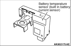
The battery temperature sensor is built in the battery current sensor. By using the change
in the thermistor resistance, the battery temperature sensor detects the ambient temperature
of the battery to output the voltage to the engine-ECU, corresponding to the ambient temperature
of the battery. The battery current acceptance varies depending on the battery temperature.
By using the sensor output voltage, the engine-ECU figures out the characteristics status of
the battery current acceptance that varies depending on the battery temperature. The engine-ECU
uses this signal for the power generation control of the alternator and the AS&G system
control. The sensor characteristics are as shown in the illustrations.
|
|
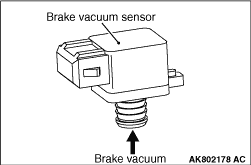
The brake vacuum sensor is installed to the brake booster assembly. To the engine-ECU,
the brake vacuum sensor outputs the voltage corresponding to the vacuum pressure stored in the
vacuum pressure chamber of the brake booster. If detecting that the vacuum pressure of the brake
booster is less than the specified value by using the sensor output voltage, the engine-ECU
prohibits the auto stop. The sensor characteristics are as shown in the illustration.
|
|
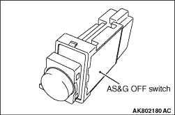
The auto stop & go (AS&G) OFF switch is installed to the switch bezel
assembly. The auto stop & go (AS&G) OFF switch, in which the illumination
lamp is built, can manually change the ON/OFF of the AS&G system. When the driver presses
the auto stop & go (AS&G) OFF switch, the auto stop & go (AS&G)
OFF switch outputs the ON signal to the engine-ECU according to the duration of pressing it.
When this signal is output into the engine-ECU more than the specified period, the engine-ECU
changes the ON/OFF of the AS&G system.
|
|
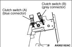
The clutch switch is installed to the two places, at the clutch pedal. The clutch switch
detects the clutch pedal position by using the contact point switch. When the clutch pedal is
not depressed, the clutch switch (A) outputs the ON signal to the engine-ECU. When the signal
is input, the engine-ECU detects that the clutch pedal is not depressed. When the clutch pedal
is fully depressed, the clutch switch (B) outputs the ON signal to the engine-ECU. When the
signal is input, the engine-ECU detects that the clutch pedal is fully depressed. The engine-ECU
uses the signal to control the AS&G system.
|
|
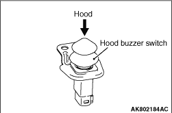
The hood buzzer switch is installed to the headlamp support cover. The hood buzzer switch
detects the open or closed status of the hood by using the contact point switch. When the hood
is closed, the hood buzzer switch outputs the high signal (switch in OFF position) to the engine-ECU.
The engine-ECU uses the signal to control the AS&G system.
|
)
)
)
)
)
)
)
)
)
)
)
)
)
)
)
)
)
)
)
)
)
)
)
)
)
)
)
)
)
)
)
)
)
)
)
)