|
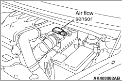
A heat-sensing type air flow sensor has been adopted. In contrast to the Karman vortex
air flow sensor, which detects the volumetric flow rate of air, this type utilizes the flow
speed dependence characteristics of heat transmission to detect the mass flow rate of air, converts
it into an amperage, and outputs it to the engine-ECU.
|
|
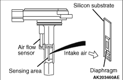
The sensing portion consists of an ultra-compact, heat-sensing membrane resistor. The
air flow sensor regulates the amperage in order to maintain a constant temperature in the heat-sensing
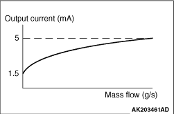
resistor. When the mass flow rate of air increases, the heat transmission from the heat-sensing
resistor to the air also increases. Therefore, the amperage that is regulated by the air flow
sensor increases. Because the heat transmission rate and the amperage are proportionate, the engine-ECU
is able to measure the air flow rate based on the amperage. The use of the ultra-compact membrane
resistor, which provides the same high-speed response as the Karman vortex air flow sensor,
enabled the compact and lightweight sensor to be installed in the air intake hose.
|
|
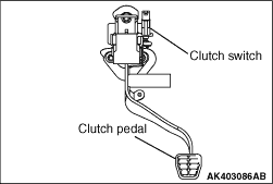
The clutch switch is a contact type switch that is mounted on the clutch pedal assembly
to detect the pressing of the clutch pedal.
When the driver presses the clutch pedal while shifting gears, the contacts of the clutch
switch close. This causes the positive battery voltage applied by the engine-ECU to be grounded
to the body via the clutch pedal assembly. Upon detecting this signal, the engine-ECU makes
fuel injection volume corrections during a shift change.
|
|
|
After turning on the ignition switch, the current is input by the engine-ECU to the alternator
L terminal. This allows the voltage regulator to be on and the field coil to be excited. When
the alternator rotates in this situation, the voltage is excited in the stator coil and the
current is output from B-terminal through the commutation diode. Also the generated voltage
is input to the voltage regulator through the commutation diode. After the electric generation
begins, the current is supplied to the field coil from this circuit. In addition, the generated
voltage is output from the alternator L terminal to the engine-ECU. This allows the engine-ECU
to detect that the electric generation begins. The engine-ECU outputs the ON signal to the combination meter
through the CAN and then turns off the charge lamp.
|
)
)
)
)
)