REMOVAL AND INSTALLATION


<FUEL TANK ASSEMBLY>


caution After the installation of the fuel tank assembly, performing the forced learning of the estimated ethanol concentration using M.U.T.-III (Refer to GROUP 00 - Precautions before Service, Forced Leaning of Estimated Ethanol Concentration ) <FFV>.
Pre-removal Operation
  • Fuel Line Pressure Reduction [Refer to GROUP 13A, On-vehicle Service - Fuel Pump Connector Disconnection (How to Reduce Pressurized Fuel Lines) ].
  • Draining Fuel.

Post-installation Operation
  • Refilling Fuel.
  • Fuel Leakage Inspection.


Removal steps
<<A>>

1.
Fuel tank pump and gauge assembly connector connection


2.
Exhaust muffler hangers


3.
Fuel filler hose connection


4.
Clip


5.
Fuel tank protector


6.
Stopper


7.
Parking brake cable clamp connection <LH side>

>>C<<
8.
Fuel main tube connection

>>C<<
9.
Fuel vapour control line tube connection

>>C<<
10.
Fuel return tube connection <4G1>
<<B>>

11.
Fuel tank band
<<B>>

12.
Fuel tank assembly

<FUEL FILLER NECK ASSEMBLY>


Removal steps


·
Rear splash shield <LH side>


1.
Fuel tank cap


2.
Fuel filler hose

>>B<<
3.
Bolt

>>A<<
4.
Fuel filler neck assembly

REMOVAL SERVICE POINTS


<<A>> FUEL TANK PUMP AND GAUGE ASSEMBLY CONNECTOR DISCONNECTION


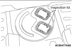
1.Remove the inspection lid.

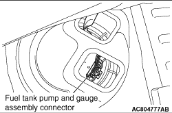
2.Disconnect the fuel tank pump and gauge assembly connector.

<<B>> FUEL TANK BAND/FUEL TANK ASSEMBLY REMOVAL


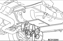
1.Support the fuel tank assembly with a transmission jack, and remove the coupling nuts of the fuel tank band and the fuel tank assembly.
2.Lower the fuel tank assembly to remove it while clearing the exhaust pipe.

INSTALLATION SERVICE POINTS


>>A<< FUEL FILLER NECK ASSEMBLY INSTALLATION


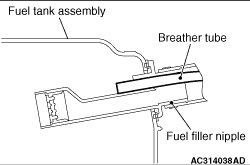
When installing the fuel filler neck assembly to the fuel tank assembly, insert the breather tube up to the upper hole of the fuel filler nipple securely.

>>B<< BOLT INSTALLATION


Wipe away the adhesive from around the bolt thread of the fuel filler neck assembly, and then tighten the bolt to the specified torque.
Tightening torque: 8.4 ± 0.8 N·m

>>C<< FUEL RETURN TUBE <4G1>/FUEL VAPOUR CONTROL LINE TUBE/FUEL MAIN TUBE INSTALLATION


caution 
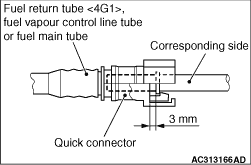
After connecting the fuel return tube <4G1>, fuel vapour control line tube or fuel main tube, slightly pull it to ensure that it is installed securely. Also confirm that there is a play approximately 3 mm.
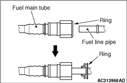
note A ring for checking engagement of the connector is fitted at the fuel line pipe side of the new fuel main tube. The ring will protrude at the pipe side when the fuel line pipe is inserted, but this is not a problem.