|
|
- Refer to Data List Reference Table
 . .
- Item 153: Clutch switch (A)
|
|
|
Q.
Is the check result normal?
|
|
|
 Intermittent malfunction (Refer to GROUP 00 - How to Use Troubleshooting/Inspection
Service Points - How to Cope with Intermittent Malfunctions ). Intermittent malfunction (Refer to GROUP 00 - How to Use Troubleshooting/Inspection
Service Points - How to Cope with Intermittent Malfunctions ).
|
|
|
|
|
Q.
Is the check result normal?
Go to Step 3 .
 Repair or replace the connector. Repair or replace the connector.
|
|
|
- Check clutch switch (A) itself (Refer to GROUP 21A - Clutch Pedal - Inspection ).
|
|
|
Q.
Is the check result normal?
|
|
|
Replace the clutch switch (A).
|
|
|
|
|
- Disconnect connector, and measure at harness side.
- Ignition switch: ON
- Voltage between terminal No. 1 and earth.
OK: System voltage
Q.
Is the check result normal?
Go to Step 6 .
|
|
Q.
Is the check result normal?
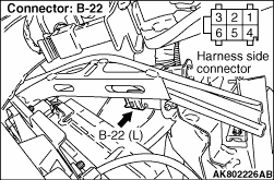
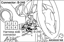
Check intermediate connectors B-210 and B-229,
and repair if necessary. If intermediate connectors are normal, check and repair harness between
B-22 (terminal No. 1) clutch switch (A) connector and B-240 (terminal No. 2) ignition switch
connector.
- Check power supply line for open/short circuit.
Repair or replace the connector.
|
|
Q.
Is the check result normal?
Go to Step 7 .
Repair or replace the connector.
|
|
- Disconnect connector, and measure at harness side.
- Ignition switch: ON
- Voltage between terminal No. 113 and earth.
OK:
System voltage (clutch pedal: release)
1 V or less (clutch pedal: depress)
Q.
Is the check result normal?
Go to Step 8 .
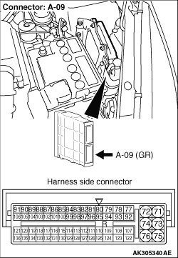
Check and repair harness between A-09 (terminal
No. 113) engine-ECU connector and B-22 (terminal No. 6) clutch switch (A) connector.
- Check output line for open/short circuit.
|
|
- Check output line for damage.
Q.
Is the check result normal?
Go to Step 9 .
Repair the damaged harness wire.
|
|
Q.
Is the check result normal?
Go to Step 10
Repair or replace the connector.
|
|
| note |
Before checking harness, check intermediate connectors B-210 and B-229, and repair if
necessary.
|
- Check power supply line for damage.
Q.
Is the check result normal?
Go to Step 11 .
Repair the damaged harness wire.
|
|
|
- Reconfirmation of diagnosis code.
|
|
|
Q.
Is the diagnosis code set?
|
|
|
Replace the engine-ECU then perform the variant coding (Refer to GROUP 00 - Precautions Before
Service - How to Perform Variant Coding ).
|
|
|
|
|
|
Intermittent malfunction (Refer to GROUP 00 - How to Use Troubleshooting/Inspection
Service Points - How to Cope with Intermittent Malfunctions ).
|
|
|
|
)
)
)
)