|
|
- Refer to Data List Reference Table
 . .
- Item No. 163: Neutral position sensor
|
|
|
Q.
Is the check result normal?
|
|
|
 Intermittent malfunction (Refer to GROUP 00 - How to Use Troubleshooting/Inspection
Service Points - How to Cope with Intermittent Malfunctions ). Intermittent malfunction (Refer to GROUP 00 - How to Use Troubleshooting/Inspection
Service Points - How to Cope with Intermittent Malfunctions ).
|
|
|
|
|
Q.
Is the check result normal?
Go to Step 3 .
 Repair or replace the connector. Repair or replace the connector.
|
|
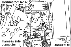
- Disconnect connector, and measure at harness side.
- Ignition switch: ON
- Voltage between terminal No. 3 and earth.
OK: 4.9 - 5.1 V
Q.
Is the check result normal?
Go to Step 7 .
Go to Step 4 .
|
|
Q.
Is the check result normal?
Go to Step 5 .
Repair or replace the connector.
|
|
- Check power supply line for open/short circuit.
Q.
Is the check result normal?
Go to Step 6 .
Repair the damaged harness wire.
|
|
|
- Refer to Data List Reference Table .
- Item No. 163: Neutral position sensor
|
|
|
Q.
Is the check result normal?
|
|
|
Intermittent malfunction (Refer to GROUP 00 - How to Use Troubleshooting/Inspection
Service Points - How to Cope with Intermittent Malfunctions ).
|
|
|
|
|
|
Replace the engine-ECU then perform the variant coding (Refer to GROUP 00 - Precautions Before
Service - How to Perform Variant Coding ).
|
|
|
|
|
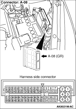
- Disconnect connector, and measure at harness side.
- Resistance between terminal No. 4 and earth.
OK: Continuity (2 Ω or less)
Q.
Is the check result normal?
Go to Step 10 .
Go to Step 8 .
|
|
Q.
Is the check result normal?
Go to Step 9 .
Repair or replace the connector.
|
|
- Check earthing line for open circuit and damage.
Q.
Is the check result normal?
Go to Step 6 .
Repair the damaged harness wire.
|
|
Q.
Is the check result normal?
Go to Step 11 .
Repair or replace the connector.
|
|
- Check power supply line for damage.
Q.
Is the check result normal?
Go to Step 12 .
Repair the damaged harness wire.
|
|
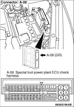
- Disconnect engine-ECU connector, and connect special tool power plant ECU
check harness (MB991987), and then measure the voltage on the check connector.
- Ignition switch: ON
- Voltage between terminal No. 11 and earth.
OK: The wave form such as the check procedure ()
with the oscilloscope must be output. When the shift lever is placed into the 1st, 3rd and 5th positions;
or when it is placed into 2nd, 4th and reverse positions, the wave form must be changed. The
output waveform must not have the noise waveform.
Q.
Is the check result normal?
Go to Step 6 .
Go to Step 13 .
|
|
- Check output line for open/short circuit and damage.
Q.
Is the check result normal?
Replace the neutral position sensor.
Repair the damaged harness wire.
|
)
)
)
)