|
Q.
Is the check result normal?
 Go to Step 2 . Go to Step 2 .
 Repair or replace the connector. Repair or replace the connector.
|
|
|
- Check starter cut relay (Refer to GROUP 16 - On-vehicle Service - Starter
Relay Check
 ). ).
|
|
|
Q.
Is the check result normal?
|
|
|
Replace the starter cut relay.
|
|
|
|
|
Q.
Is the check result normal?
Go to Step 4 .
Repair or replace the connector.
|
|
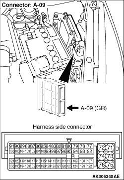
- Disconnect connector, and measure at harness side.
- Voltage between terminal No. 116 and earth.
OK: System voltage
Q.
Is the check result normal?
Go to Step 5 .
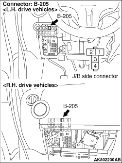
Check intermediate connector B-212, and repair
if necessary. If intermediate connector is normal, check and repair harness between B-205 (terminal
No. 2) starter cut relay connector and A-09 (terminal No. 116) engine-ECU connector.
- Check signal line for short circuit.
|
|
| note |
Before checking harness, check intermediate connector B-209, and repair if necessary.
|
- Check power supply line for short circuit.
Q.
Is the check result normal?
Go to Step 6 .
Repair the damaged harness wire.
|
|
|
- Reconfirmation of diagnosis code.
|
|
|
Q.
Is diagnosis code set?
|
|
|
Intermittent malfunction (Refer to GROUP 00 - How to Use Troubleshooting/Inspection
Service Points - How to Cope with Intermittent Malfunctions ).
|
|
|
|
)
)
)