|
|
- Refer to Data List Reference Table
 . .
- Item No. 161: Brake vacuum sensor
|
|
|
Q.
Is the check result normal?
|
|
|
 Intermittent malfunction (Refer to GROUP 00 - How to Use Troubleshooting/Inspection
Service Points - How to Cope with Intermittent Malfunctions ). Intermittent malfunction (Refer to GROUP 00 - How to Use Troubleshooting/Inspection
Service Points - How to Cope with Intermittent Malfunctions ).
|
|
|
|
|
Q.
Is the check result normal?
Go to Step 3 .
 Repair or replace the connector. Repair or replace the connector.
|
|
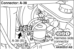
- Disconnect connector, and measure at harness side.
- Ignition switch: ON
- Voltage between terminal No. 3 and earth.
OK: 4.9 - 5.1 V
Q.
Is the check result normal?
Go to Step 7 .
Go to Step 4 .
|
|
Q.
Is the check result normal?
Go to Step 5 .
Repair or replace the connector.
|
|
- Check power supply line for open/short circuit.
Q.
Is the check result normal?
Go to Step 6 .
Repair the damaged harness wire.
|
|
|
- Refer to Data List Reference Table .
- Item No. 161: Brake vacuum sensor
|
|
|
Q.
Is the check result normal?
|
|
|
Intermittent malfunction (Refer to GROUP 00 - How to Use Troubleshooting/Inspection
Service Points - How to Cope with Intermittent Malfunctions ).
|
|
|
|
|
|
Replace the engine-ECU then perform the variant coding (Refer to GROUP 00 - Precautions Before
Service - How to Perform Variant Coding ).
|
|
|
|
|
- Disconnect connector, and measure at harness side.
- Resistance between terminal No. 2 and earth.
OK: Continuity (2 Ω or less)
Q.
Is the check result normal?
Go to Step 10 .
Go to Step 8 .
|
|
Q.
Is the check result normal?
Go to Step 9 .
Repair or replace the connector.
|
|
- Check earthing line for open circuit and damage.
Q.
Is the check result normal?
Go to Step 6 .
Repair the damaged harness wire.
|
|
Q.
Is the check result normal?
Go to Step 11 .
Repair or replace the connector.
|
|
- Check power supply line for damage.
Q.
Is the check result normal?
Go to Step 12 .
Repair the damaged harness wire.
|
|
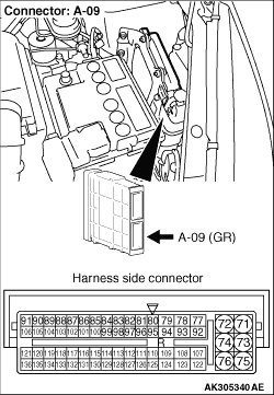
- Use special tool test harness (MB991658) to connect connector, and measure
at pick-up harness.
- Engine: Warming up, idle
- Voltage between terminal No. 1 and earth.
OK: The voltage is reduced according to the brake depressing amount. (turn the ignition
switch ON after the engine stops from the idling. Depress the brake pedal several times.)
Q.
Is the check result normal?
Go to Step 14 .
Go to Step 13 .
|
|
- Check output line for short circuit.
Q.
Is the check result normal?
Replace the brake vacuum sensor.
Repair the damaged harness wire.
|
|
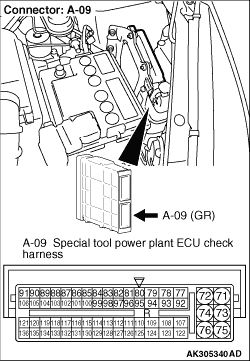
- Disconnect engine-ECU connector, and connect special tool power plant ECU
check harness (MB991987), and then measure the voltage on the check connector.
- Engine: Warming up, idle
- Voltage between terminal No. 128 and earth.
OK: The voltage is reduced according to the brake depressing amount. (turn the ignition
switch ON after the engine stops from the idling. Depress the brake pedal several times.)
Q.
Is the check result normal?
Go to Step 6 .
Go to Step 15 .
|
|
Q.
Is the check result normal?
Check and repair check harness between A-38 (terminal
No. 1) brake vacuum sensor connector and A-09 (terminal No. 128) engine-ECU connector.
- Check output line for open circuit and damage.
Repair or replace the connector.
|
)
)
)
)