|
|
- Refer to Data List Reference Table
 . .
- Item No. 159: Battery current sensor
|
|
|
Q.
Is the check result normal?
|
|
|
 Intermittent malfunction (Refer to GROUP 00 - How to Use Troubleshooting/Inspection
Service Points - How to Cope with Intermittent Malfunctions ). Intermittent malfunction (Refer to GROUP 00 - How to Use Troubleshooting/Inspection
Service Points - How to Cope with Intermittent Malfunctions ).
|
|
|
|
|
Q.
Is the check result normal?
Go to Step 3 .
 Repair or replace the connector. Repair or replace the connector.
|
|
|
- Check battery current sensor itself (Refer to GROUP 54A - Inspection - Battery
Current Sensor Check <Vehicles with AS&G system> ).
|
|
|
Q.
Is the check result normal?
|
|
|
Replace the battery current sensor.
|
|
|
|
|
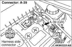
- Disconnect connector, and measure at harness side.
- Ignition switch: ON
- Voltage between terminal No. 1 and earth.
OK: 4.9 - 5.1 V
Q.
Is the check result normal?
Go to Step 8 .
Go to Step 5 .
|
|
Q.
Is the check result normal?
Go to Step 6 .
Repair or replace the connector.
|
|
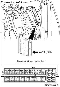
- Check power supply line for open/short circuit.
Q.
Is the check result normal?
Go to Step 7 .
Repair the damaged harness wire.
|
|
|
- Refer to Data List Reference Table .
- Item No. 159: Battery current sensor
|
|
|
Q.
Is the check result normal?
|
|
|
Intermittent malfunction (Refer to GROUP 00 - How to Use Troubleshooting/Inspection
Service Points - How to Cope with Intermittent Malfunctions ).
|
|
|
|
|
|
Replace the engine-ECU then perform the variant coding (Refer to GROUP 00 - Precautions Before
Service - How to Perform Variant Coding ).
|
|
|
|
|
- Disconnect connector, and measure at harness side.
- Resistance between terminal No. 3 and earth.
OK: Continuity (2 Ω or less)
Q.
Is the check result normal?
Go to Step 11 .
Go to Step 9 .
|
|
Q.
Is the check result normal?
Go to Step 10 .
Repair or replace the connector.
|
|
- Check earthing line for open circuit and damage.
Q.
Is the check result normal?
Go to Step 7 .
Repair the damaged harness wire.
|
|
Q.
Is the check result normal?
Go to Step 12 .
Repair or replace the connector.
|
|
- Check power supply line for damage.
Q.
Is the check result normal?
Go to Step 13 .
Repair the damaged harness wire.
|
|
- Check output line for open/short circuit and damage.
Q.
Is the check result normal?
Go to Step 7 .
Repair the damaged harness wire.
|
)
)
)