|
Q.
Is the check result normal?
 Go to Step 2 . Go to Step 2 .
 Repair. Repair.
|
|
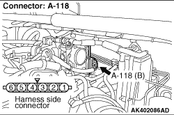
- Disconnect connector, and measure at electronic-controlled throttle
valve side.
- Resistance between terminal No. 5 and No. 6.
OK: 0.3 - 100 kΩ (at 20 °C)
Q.
Is the check result normal?
Go to Step 3 .
Replace throttle body assembly.
|
|
Q.
Is the check result normal?
Go to Step 4 .
Repair.
|
|
- Check output line for short circuit and damage.
Q.
Is the check result normal?
Go to Step 5 .
Repair.
|
|
- Check output line for short circuit and damage.
Q.
Is the check result normal?
Go to Step 6 .
Repair.
|
|
|
Q.
Is the check result normal?
|
|
|
Intermittent malfunction (Refer to GROUP 00 - How to Use Troubleshooting/Inspection
Service Points - How to Cope with Intermittent Malfunctions  ). ).
|
|
|
|
|
|
Replace engine-ECU then perform the variant coding (Refer to GROUP 00 - Precautions
Before Service - How to Perform Variant Coding ).
|
|
|
|
)
)
)