|
|
Q.
Is any other diagnosis code than P0125 output?
|
|
|
 Inspection chart for diagnosis code (Refer to Inspection chart for diagnosis code (Refer to  ). ).
|
|
|
|
|
|
- Refer to Data List Reference Table .
|
|
|
- Item No. 8: Engine coolant temperature sensor
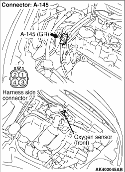
- Item No. 9: Oxygen sensor (front)
- Item No. 10: Oxygen sensor (rear)
- Item No. 80: Air flow sensor
|
|
|
Q.
Are the check results normal?
|
|
|
 Perform the diagnosis code classified check procedure for the sensor that has
shown an abnormal data valve (Refer to Inspection Chart for Diagnosis Code ). Perform the diagnosis code classified check procedure for the sensor that has
shown an abnormal data valve (Refer to Inspection Chart for Diagnosis Code ).
|
|
|
|
|
|
- Refer to Data List Reference Table .
|
|
|
- Item No. 79: Barometric pressure sensor
|
|
|
Q.
Is the check result normal?
|
|
|
Replace the engine-ECU then perform the variant coding (Refer to GROUP 00 - Precautions
Before Service - How to Perform Variant Coding ).
|
|
|
|
|
|
Q.
Is the check result normal?
|
|
|
Repair for intake of air from gaps in gasket, seals, etc.
|
|
|
|
|
|
Q.
Is the check result normal?
|
|
|
Repair for leakage of exhaust emission from exhaust manifold.
|
|
|
|
|
|
Q.
Is the check result normal?
|
|
|
Clean throttle body (throttle valve portion) (Refer to ).
|
|
|
|
|
Q.
Is the check result normal?
Go to Step 8 .
Repair or replace the connector.
|
|
|
- Check oxygen sensor (front) itself (Refer to ).
|
|
|
Q.
Is the check result normal?
|
|
|
Replace the oxygen sensor (front).
|
|
|
|
|
- Check output line for damage.
Q.
Is the check result normal?
Go to Step 10 .
Repair the damaged harness wire.
|
|
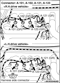
- A-101 (No.1 injector connector)
- A-102 (No.2 injector connector)
- A-123 (No.3 injector connector)
- A-121 (No.4 injector connector)
Q.
Is the check result normal?
Go to Step 11 .
Repair or replace the connector.
|
|
|
- Check Injector itself (Refer to ).
|
|
|
Q.
Is the check result normal?
|
|
Q.
Is the check result normal?
Go to Step 13 .
Repair or replace the connector.
|
|
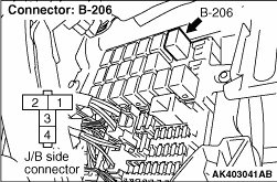
- Check harness between B-206 (terminal No. 4) engine control
relay connector and A-101 (terminal No. 1) No. 1 injector connector.
- Check harness between B-206 (terminal No. 4) engine control relay connector and
A-102 (terminal No. 1) No. 2 injector connector.
- Check harness between B-206 (terminal No. 4) engine control relay connector and
A-123 (terminal No. 1) No. 3 injector connector.
- Check harness between B-206 (terminal No. 4) engine control relay connector and
A-121 (terminal No. 1) No. 4 injector connector.
| note |
Before checking harness, check intermediate connectors B-212 and A-36, and repair if necessary.
|
- Check power supply line for damage.
Q.
Are the check results normal?
Go to Step 14 .
Repair the damaged harness wire.
|
|
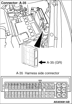
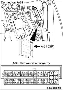
- Check harness between A-101 (terminal No. 2) No.
1 injector connector and A-34 (terminal No. 8) engine-ECU connector.
- Check harness between A-102 (terminal No. 2) No. 2 injector connector and A-34 (terminal
No. 9) engine-ECU connector.
- Check harness between A-123 (terminal No. 2) No. 3 injector connector and A-34 (terminal
No. 23) engine-ECU connector.
- Check harness between A-121 (terminal No. 2) No. 4 injector connector and A-34 (terminal
No. 24) engine-ECU connector.
- Check earthing line for damage.
Q.
Are the check results normal?
Go to Step 15 .
Repair the damaged harness wire.
|
|
|
- Fuel pressure measurement (Refer to Fuel Pressure Test ).
|
|
|
Q.
Is the check result normal?
|
|
|
Replace the engine-ECU then perform the variant coding (Refer to GROUP 00 - Precautions
Before Service - How to Perform Variant Coding ).
|
|
|
|
|
|
Repair the fuel pressure.
|
|
|
|
)
)
)
)
)