|
Q.
Is the check result normal?
 Go to Step 2 . Go to Step 2 .
 Repair or replace the connector. Repair or replace the connector.
|
|
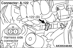
- Disconnect connector, and measure at harness side.
- Resistance between terminal No. 1 and earth.
OK: Continuity (2 Ω or less)
Q.
Is the check result normal?
Go to Step 6 .
Go to Step 3 .
|
|
Q.
Is the check result normal?
Go to Step 4 .
Repair or replace the connector.
|
|
- Check earthing line for open circuit and damage.
Q.
Is the check result normal?
Go to Step 5 .
Repair the damaged harness wire.
|
|
|
- After replacing the detonation sensor, re-check the trouble symptoms.
|
|
|
Q.
Does trouble symptom persist?
|
|
|
Replace the engine-ECU then perform the variant coding (Refer to GROUP 00 -
Precautions
Before Service -
How to Perform Variant Coding  ). ).
|
|
|
|
|
|
Intermittent malfunction (Refer to GROUP 00 -
How to Use Troubleshooting/Inspection
Service Points -
How to Cope with Intermittent Malfunctions ).
|
|
|
|
|
- Disconnect connector, and measure at harness side.
- Ignition switch: ON
- Voltage between terminal No. 2 and earth.
OK: 4.5 -
4.9 V
Q.
Is the check result normal?
GO to Step 11 .
Go to Step 7 .
|
|
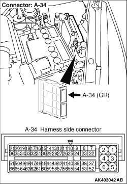
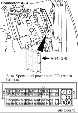
- Disconnect engine-ECU connector, and connect special tool power plant ECU
check harness (MB991987), and then measure the voltage on the check connector.
- Disconnect A-122 detonation sensor.
- Ignition switch: ON
- Voltage between terminal No. 20 and earth.
OK: 4.5 -
4.9 V
Q.
Is the check result normal?
Go to Step 8 .
Go to Step 9 .
|
|
Q.
Is the check result normal?
Check and repair harness between A-122 (terminal
No. 2) detonation sensor connector and A-34 (terminal No. 20) engine-ECU connector.
- Check output line for open circuit.
Repair or replace the connector.
|
|
Q.
Is the check result normal?
Go to Step 10 .
Repair or replace the connector.
|
|
- Check output line for short circuit.
Q.
Is the check result normal?
Go to Step 5 .
Repair the damaged harness wire.
|
|
- Check output line for damage.
Q.
Is the check result normal?
Go to Step 12 .
Repair the damaged harness wire.
|
|
|
- Reconfirmation of diagnosis code.
|
|
|
Q.
Is the diagnosis code set?
|
|
|
Intermittent malfunction (Refer to GROUP 00 -
How to Use Troubleshooting/Inspection
Service Points -
How to Cope with Intermittent Malfunctions ).
|
|
|
|
|
|
- After replacing the detonation sensor, re-check the trouble symptoms.
|
|
|
Q.
Does trouble symptom persist?
|
|
|
Replace the engine-ECU then perform the variant coding (Refer to GROUP 00 -
Precautions
Before Service -
How to Perform Variant Coding ).
|
|
|
|
)
)
)
)