|
|
- Item No. 8: Engine coolant temperature sensor
|
|
|
OK:
Engine cold state: At ambient temperature (atmospheric temperature) or equivalent.
Engine hot state: At 80 -
120°C
|
|
|
Q.
Is the check result normal?
|
|
|
 Intermittent malfunction (Refer to GROUP 00 -
How to Use Troubleshooting/Inspection
Service Points -
How to Cope with Intermittent Malfunctions Intermittent malfunction (Refer to GROUP 00 -
How to Use Troubleshooting/Inspection
Service Points -
How to Cope with Intermittent Malfunctions  ). ).
|
|
|
|
|
Q.
Is the check result normal?
Go to Step 3 .
 Repair or replace the connector. Repair or replace the connector.
|
|
- Disconnect connector, and measure at sensor side.
- Resistance between terminal No. 1 and No. 2.
OK:
Engine coolant temperature at -20°C: 14 -
17 kΩ
Engine coolant temperature at 0°C: 5.1 -
6.5 kΩ
Engine coolant temperature at 20°C: 2.1 -
2.7 kΩ
Engine coolant temperature at 40°C: 0.9 -
1.3 kΩ
Engine coolant temperature at 60°C: 0.48 -
0.68 kΩ
Engine coolant temperature at 80°C: 0.26 -
0.36 kΩ
Q.
Is the check result normal?
Go to Step 4 .
Replace the engine coolant temperature sensor.
|
|
- Disconnect connector and measure at harness side.
- Voltage between terminal No. 2 and earth.
OK: Continuity (2 Ω or less)
Q.
Is the check result normal?
Go to Step 8 .
Go to Step 5 .
|
|
|
Q.
Is the check result normal?
|
|
Go to Step 6 .
Repair or replace the connector.
|
|
- Check earthing line for open circuit and damage.
Q.
Is the check result normal?
Go to Step 7 .
Repair the damaged harness wire.
|
|
|
- Item No. 8: Engine coolant temperature sensor
|
|
|
OK:
Engine cold state: At ambient temperature (atmospheric temperature) or equivalent.
Engine hot state: At 80 -
120 °C
|
|
|
Q.
Is the check result normal?
|
|
|
Intermittent malfunction (Refer to GROUP 00 -
How to Use Troubleshooting/Inspection
Service Points -
How to Cope with Intermittent Malfunctions ).
|
|
|
|
|
|
Replace the engine-ECU then perform the variant coding (Refer to GROUP 00 -
Precautions
Before Service -
How to Perform Variant Coding ).
|
|
|
|
|
- Disconnect connector, and measure at harness side.
- Ignition switch: ON
- Voltage between terminal No. 1 and earth.
OK: 4.5 -
4.9 V
Q.
Is the check result normal?
Go to Step 13 .
Go to Step 9 .
|
|
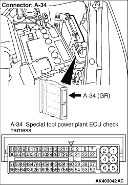
- Disconnect engine-ECU connector, and connect special tool power plant ECU
check harness (MB991987), and then measure the voltage on the check connector.
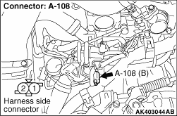
- Disconnect A-108 engine coolant temperature sensor connector.
- Ignition switch: ON
- Voltage between terminal No. 14 and earth.
OK: 4.5 -
4.9 V
Q.
Is the check result normal?
Go to Step 10 .
Go to Step 11 .
|
|
Q.
Is the check result normal?
Check and repair harness between A-108 (terminal No.
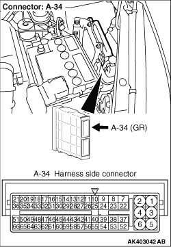
1) engine coolant temperature sensor connector and A-34 (terminal No. 14) engine-ECU connector.
- Check output line for open circuit.
Repair or replace the connector.
|
|
Q.
Is the check result normal?
Go to Step 12 .
Repair or replace the connector.
|
|
- Check output line for short circuit.
Q.
Is the check result normal?
Go to Step 7 .
Repair the damaged harness wire.
|
|
- Use special tool test harness (MB991658) to connect connector,
and measure at pick-up harness.
- Ignition switch: ON
- Voltage between terminal No. 1 and earth.
OK:
Engine coolant temperature at -20°C: 3.9 -
4.5 V
Engine coolant temperature at 0°C: 3.2 -
3.8 V
Engine coolant temperature at 20°C: 2.3 -
2.9 V
Engine coolant temperature at 40°C: 1.3 -
1.9 V
Engine coolant temperature at 60°C: 0.7 -
1.3 V
Engine coolant temperature at 80°C: 0.3 -
0.9 V
Q.
Is the check result normal?
Go to Step 7 .
Go to Step 14 .
|
|
Q.
Is the check result normal?
Go to Step 15 .
Repair or replace the connector.
|
|
- Check output line for damage.
Q.
Is the check result normal?
Go to Step 7 .
Repair or replace the connector.
|
)
)
)
)