|
|
- Item No. 155: Hood buzzer switch
|
|
|
OK:
Closed (hood: close)
Open (hood: open)
|
|
|
Q.
Is the check result normal?
|
|
|
 Check combination meter (Refer to GROUP 54A - Combination Meter - Check
Chart for Trouble Symptoms Check combination meter (Refer to GROUP 54A - Combination Meter - Check
Chart for Trouble Symptoms  <COLT>, <COLT
CZ3>). <COLT>, <COLT
CZ3>).
|
|
|
|
|
Q.
Is the check result normal?
Go to Step 3 .
 Repair or replace the connector. Repair or replace the connector.
|
|
|
- Check hood buzzer switch (Refer to GROUP 42 - Hood - Inspection ).
|
|
|
Q.
Is the check result normal?
|
|
|
Replace the hood buzzer switch
|
|
|
|
|
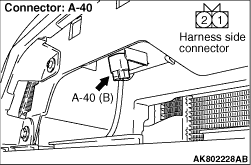
- Disconnect connector, and measure at harness side.
- Resistance between terminal No. 2 and earth.
OK: Continuity (2 Ω or less)
Q.
Is the check result normal?
Go to Step 5 .
Check and repair harness between A-40 (terminal
No. 2) hood buzzer switch connector and body earth.
- Check earthing line for open circuit and damage
|
|
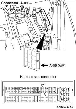
- Disconnect connector, and measure at harness side.
- Ignition switch: ON
- Voltage between terminal No. 1 and earth.
OK: System voltage
Q.
Is the check result normal?
Go to Step 9 .
Go to Step 6 .
|
|
Q.
Is the check result normal?
Go to Step 7 .
Repair or replace the connector.
|
|
- Check output line for open/short circuit.
Q.
Is the check result normal?
Go to Step 8 .
Repair the damaged harness wire.
|
|
|
- Item No. 155: Hood buzzer switch
|
|
|
OK:
Closed (hood: close)
Open (hood: open)
|
|
|
Q.
Is the check result normal?
|
|
|
Intermittent malfunction (Refer to GROUP 00 - How to Use Troubleshooting/Inspection
Service Points - How to Cope with Intermittent Malfunctions ).
|
|
|
|
|
|
Replace the engine-ECU then perform the variant coding (Refer to GROUP 00 - Precautions
Before Service - How to Perform Variant Coding ).
|
|
|
|
|
Q.
Is the check result normal?
Go to Step 10 .
Repair or replace the connector.
|
|
- Check output line for damage.
Q.
Is the check result normal?
Go to Step 8 .
Repair the damaged harness wire.
|
)
)
)