Inspection Procedure
32: Auto Stop & Go (AS&G) System Abnormal (Auto Stop Not Carried Out) <Vehicles
with AS&G system>
OPERATION
- Refer to Code No. P0622: Alternator FR Terminal System

- Refer to Inspection Procedure 26: Battery Run Down
COMMENTS ON TROUBLE SYMPTOM
- The failed engine and the AS&G system malfunction can possibly cause
this. The engine-ECU, however, can possibly prohibit the auto stop, depending on the vehicle
status or the ambient conditions.
PROBABLE CAUSES
- Failed AS&G system
- Failed seat belt reminder function
- Failed hood buzzer switch
- Shorted alternator G terminal circuit, or connector damage
- Shorted alternator FR terminal circuit, or connector damage
- Failed battery
- Failed engine-ECU
|
|
STEP 1. Confirm the vehicle status and the ambient conditions.
|
|
|
- Confirm the vehicle status or the ambient conditions to check whether the
auto stop should be carried out or not. (Refer to Technical Information Manual)
|
|
|
Q.
Are the conditions for prohibiting the auto stop satisfied?
|
|
|
 Check end. Check end.
|
|
|
|
|
|
 Go to Step 2 . Go to Step 2 .
|
|
|
|
|
|
STEP 2. M.U.T.-III diagnosis code
|
|
|
Q.
Is the diagnosis code set?
|
|
|
Inspection chart for diagnosis code (Refer to ).
|
|
|
|
|
|
Go to Step 3 .
|
|
|
|
|
|
STEP 3. M.U.T.-III other system diagnosis code
|
|
|
- Confirm whether the diagnosis codes are output from combination meter.
|
|
|
Q.
Is the diagnosis code output?
|
|
|
Perform the troubleshooting of combination meter (Refer to GROUP 54A - Combination
meter - Check Chart for Diagnosis Codes <COLT>, <COLT
CZ3>)
|
|
|
|
|
|
Go to Step 4 .
|
|
|
|
|
|
STEP 4. M.U.T.-III data list
|
|
|
- Refer to Data List Reference Table .
- Item No. 8: Engine coolant temperature sensor
- Item No. 161: Brake vacuum sensor
|
|
|
Q.
Are the check results normal?
|
|
|
Go to Step 5 .
|
|
|
|
|
|
Perform the diagnosis code classified check procedure for the sensor that has
shown an abnormal data value (Refer to Inspection Chart for Diagnosis Code ).
|
|
|
|
|
|
STEP 5. M.U.T.-III data list
|
|
|
- Refer to Data List Reference Table .
- Item No. 163: Neutral position sensor
|
|
|
Q.
Are the check results normal?
|
|
|
Go to Step 7 .
|
|
|
|
|
|
Go to Step 6 .
|
|
|
|
|
|
STEP 6. Neutral position sensor check
|
|
|
- Ignition switch: ON
- Place the shift lever in the neutral position.
|
|
|
| note |
During this time, do not touch the shift lever. Do not start the engine. Be careful not
to cause the vibration in the vehicle.
|
|
|
|
- Item No. 163: Neutral position sensor
|
|
|
Q.
Is another value shown except "5%" ?
|
|
|
Check the circuit of the neutral position sensor (Refer to Code No. P0820 ).
|
|
|
|
|
|
Confirm the installation statuses of both of the neutral position sensor and the
shift cover Cpl. permanent magnet. If they are normally installed, replace the neutral position
sensor because the neutral position sensor can possibly be failed.
|
|
|
|
|
|
STEP 7. Confirm the driver’s seat belt indicator lamp is extinguished.
|
|
|
- Ignition switch: ON
- Confirm the driver’s seat belt indicator lamp is extinguished in the combination
meter when the driver’s seatbelt is fastened.
|
|
|
Q.
Is the driver’s seat belt indicator lamp extinguished?
|
|
|
Go to Step 8 .
|
|
|
|
|
|
Check seat belt reminder function circuit (Refer to GROUP 54B - Symptom
Procedures - Buzzer - Seat Belt Reminder Function Does Not Work Normally )
|
|
|
|
|
|
STEP 8. Confirm the AS&G indicator lamp is extinguished.
|
|
|
- Ignition switch: ON
- When the hood is closed, confirm the AS&G indicator lamp is extinguished
in the combination meter.
|
|
|
Q.
Is the AS&G indicator lamp extinguished?
|
|
|
Go to Step 9 .
|
|
|
|
|
|
Check hood buzzer switch circuit (Refer to Inspection Procedure 35 ).
|
|
|
|
|
|
STEP 9. M.U.T.-III data list
|
|
|
- Item No. 156: Neutral position learning
|
|
|
OK: Completed (ignition switch: ON)
|
|
|
Q.
Is the check result normal?
|
|
|
Go to Step 10 .
|
|
|
|
|
|
Carry out the learning of the neutral position. (Refer to GROUP 00 - Precautions
before Service - Learning Procedure For Neutral Position ).
|
|
|
|
|
|
STEP 10. Check the software version of the engine-ECU.
|
|
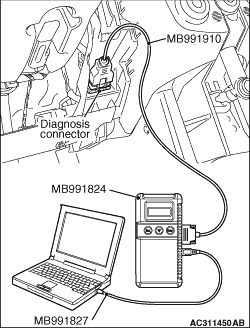
Use the following procedures to check the software version of the engine-ECU.
(1)After the ignition switch is in "LOCK" (OFF) position, connect the M.U.T.-III to
the diagnosis connector.
(2)Turn the ignition switch to the "ON" position.
(3)Select "MPI/GDI/DIESEL" from System select Screen of the M.U.T.-III.
(4)Select "Special Function" from MPI/GDI/DIESEL Screen.
(5)Select "ECU Information" from Special Function Screen.
(6)Check "Software Version" on ECU Information Screen.
Q.
Does the software version show "046814"?
Charge the battery (Refer to GROUP 54A - Battery - On-vehicle
Service - Charging ). As soon as the battery is charged, go
to Step 17 .
Go to Step 11 .
|
|
|
STEP 11. M.U.T.-III data list
|
|
|
- Item No. 166: Battery deteriorated odometer (Last)
- Item No. 167: Battery deteriorated odometer (2nd Last)
- Item No. 168: Battery deteriorated odometer (3rd Last)
|
|
|
OK: 0 (Ignition switch: ON)
|
|
|
| note |
If the situation falls under any of the following items, go to "NO" whether or not the
item on the screen.
- After a malfunction occurs, the negative (-) cable is removed from the battery once.
- The odometer shown on the combination meter is beyond 262,140 km.
|
|
|
|
Q.
Is the check result normal?
|
|
|
Go to Step 12 .
|
|
|
|
|
|
Go to Step 16 .
|
|
|
|
|
|
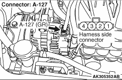
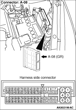
STEP 12. Connector check: A-127 alternator connector and A-08 engine-ECU
connector
|
|
Q.
Are the check results normal?
Go to Step 13 .
Repair or replace the connector.
|
|
|
STEP 13. Check harness between A-08 (terminal No. 54) engine-ECU connector
and A-127 (terminal No. 4) alternator connector.
|
|
- Check output line for short circuit.
Q.
Is the check result normal?
Go to Step 14 .
Repair the damaged harness wire.
|
|
|
STEP 14. Check harness between A-08 (terminal No. 53) engine-ECU connector
and A-127 (terminal No. 1) alternator connector.
|
|
- Check output line for short circuit.
Q.
Is the check result normal?
Go to Step 15 .
Repair the damaged harness wire.
|
|
|
STEP 15. Check the trouble symptoms.
|
|
|
Q.
Does trouble symptom persist?
|
|
|
Replace the engine-ECU then perform the variant coding (Refer to GROUP 00 - Precautions
Before Service - How to Perform Variant Coding ).
|
|
|
|
|
|
Intermittent malfunction (Refer to GROUP 00 - How to Use Troubleshooting/Inspection
Service Points - How to Cope with Intermittent Malfunctions ).
|
|
|
|
|
|
STEP 16. M.U.T.-III data list
|
|
|
- Disconnect the negative (-) cable from the battery
(this can delete backup data).
- Charge the battery (Refer to GROUP 54A - Battery - On-vehicle
Service - Charging ). As soon as the battery is charged, leave
the engine idling.
- Item No. 165: Charging battery mode flag
- Lights and all accessories: OFF
|
|
|
OK: ON → OFF (after approximately 10 minutes)
|
|
|
Q.
Is the check result normal?
|
|
|
Go to Step 23 .
|
|
|
|
|
|
Go to Step 17 .
|
|
|
|
|
|
STEP 17. M.U.T.-III data list
|
|
|
- Item No. 2: Power supply voltage
- Engine: Idling
- Lights and all accessories: OFF
|
|
|
Q.
Is the check result normal?
|
|
|
Go to Step 21 .
|
|
|
|
|
|
Go to Step 18 .
|
|
|
|
|
|
STEP 18. Connector check: A-127 alternator connector and A-08 engine-ECU
connector
|
|
Q.
Are the check results normal?
Go to Step 19 .
Repair or replace the connector.
|
|
|
STEP 19. Check harness between A-08 (terminal No. 54) engine-ECU connector
and A-127 (terminal No. 4) alternator connector.
|
|
- Check output line for short circuit.
Q.
Is the check result normal?
Go to Step 20 .
Repair the damaged harness wire.
|
|
|
STEP 20. Check harness between A-08 (terminal No. 53) engine-ECU connector
and A-127 (terminal No. 1) alternator connector.
|
|
- Check output line for short circuit.
Q.
Is the check result normal?
Check battery (Refer to GROUP 54A - Battery - On-vehicle Service - Battery
Test ).
Repair the damaged harness wire.
|
|
|
STEP 21. M.U.T.-III data list
|
|
|
- Item No. 159: Battery current sensor
- Engine: Idling
- Lights and all accessories: OFF
|
|
|
Q.
Is the check result normal?
|
|
|
Go to Step 23 .
|
|
|
|
|
|
Go to Step 22 .
|
|
|
|
|
|
STEP 22. Check battery current sensor itself.
|
|
|
- Check battery current sensor itself (Refer to GROUP 54A - Inspection - Battery
Current Sensor Check <Vehicles with AS&G system> ).
|
|
|
Q.
Is the check result normal?
|
|
|
Check battery (Refer to GROUP 54A - Battery - On-vehicle Service - Battery
Test ).
|
|
|
|
|
|
Replace the battery current sensor.
|
|
|
|
|
|
STEP 23. Judge the battery life.
|
|
|
(1)Turn the ignition switch to "ON" position (But do not start the engine). Fulfill
the following conditions for 120 seconds and discharge the battery.
- Head lamp switch: ON
- Rear window defogger switch: ON
|
|
|
(2)Run the engine for 10 seconds after the engine start and check on the battery deterioration
with M.U.T.-III data lists.
- Item No. 152: Battery deterioration flag
OK: OFF (engine: idle operation)
|
|
|
(3)After checking that the M.U.T.-III data list item No. 152 is displayed, swiftly
turn the ignition switch to "LOCK" (OFF) position and leave it for 10 seconds.
|
|
|
(4)Repeat Steps 1-3 four times. Check that M.U.T.-III always shows "OFF".
|
|
|
Q.
Is the check result normal?
|
|
|
Recharge the battery because the battery is discharged during the check. (Refer
to GROUP 54A - Battery - On-vehicle Service - Charging ). After
the battery is charged, go to Step 15 .
|
|
|
|
|
|
Replace the battery.
|
|
|
|
)
)
)