|
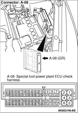
- Engine-ECU connector, and connect special tool power plant ECU check harness
(MB991987), and then measure the voltage on the check connector.
- Voltage between terminal No. 50 and earth.
OK:
System voltage (Idling after warming up)
0.5 V or less (Ignition switch: ON)
Q.
Is the check result normal?
 Check combination meter (Refer to GROUP 54A - Combination Meter - Check
Chart for Trouble Symptoms Check combination meter (Refer to GROUP 54A - Combination Meter - Check
Chart for Trouble Symptoms  <COLT>, <COLT
CZ3>). <COLT>, <COLT
CZ3>).
 Go to Step 2 . Go to Step 2 .
|
|
Q.
Is the check result normal?
Go to Step 3 .
Repair or replace the connector.
|
|
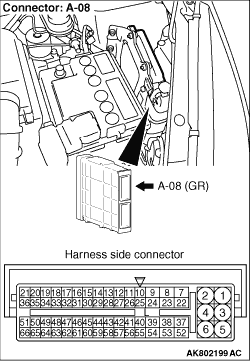
- Check output line for open/short circuit and damage.
Q.
Is the check result normal?
Go to step 4 .
Repair.
|
|
Q.
Is the check result normal?
Go to step 5 .
Repair.
|
|
|
- Oil pressure check (Refer to GROUP 12 - On-Vehicle Service - Oil
Pressure Check ).
|
|
|
Q.
Is the check result normal?
|
|
|
- After replacing the oil pressure switch, re-check the trouble symptoms.
|
|
|
Q.
Does trouble symptom persist?
|
|
|
Replace the engine-ECU then perform the variant coding (Refer to GROUP 00 - Precautions
Before Service - How to Perform Variant Coding ).
|
|
|
|
)
)
)
)