|
|
 Inspection chart for diagnosis code (Refer to Inspection chart for diagnosis code (Refer to  ). ).
|
|
|
|
|
|
- Engine: Idling
- A/C set temperature:
Maximum Cool when temperature in cabin is 25°C
or more
Maximum Hot when temperature in cabin is 25°C or less
|
|
|
OK:
Magnet clutch active (when A/C is ON)
Magnet clutch inactive (when A/C is OFF)
|
|
|
Q.
Is the check result normal?
|
|
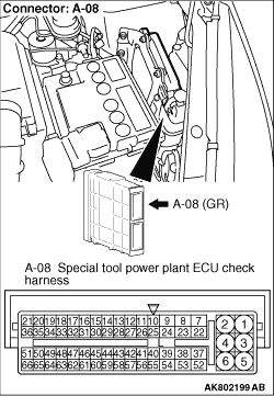
- Disconnect engine-ECU connector, and connect special tool power plant ECU
check harness (MB991987), and then measure the voltage on the check connector.
- Engine: Running at idle
- A/C set temperature:
Maximum Cool when temperature in cabin is 25°C
or more.
Maximum Hot when temperature in cabin is 25°C or less.
- Voltage between terminal No. 39 and earth.
OK:
Voltage decreases (turn the A/C switch ON)
System voltage (turn the A/C switch OFF)
Q.
Is the check result normal?
Check A/C system (Refer to GROUP 55B - Troubleshooting - Check
Chart for Diagnosis Codes ).
 Check A/C compressor relay system (Refer to Inspection Procedure 31 ). Check A/C compressor relay system (Refer to Inspection Procedure 31 ).
|
|
|
- Check charged amount of A/C refrigerant (Refer to GROUP 55B - On-vehicle
Service - Sight Glass Refrigerant Level Test ).
|
|
|
Q.
Is the check result normal?
|
|
|
Check A/C system (Refer to GROUP 55B - Troubleshooting - Check
Chart for Diagnosis Codes ).
|
|
|
|
|
|
Adjust charged amount of A/C refrigerant.
|
|
|
|
)