|
|
 Inspection chart for diagnosis code (Refer to Inspection chart for diagnosis code (Refer to  ). ).
|
|
|
|
|
|
- Refer to Data List Reference Table .
- Item No. 6: Intake air temperature sensor
- Item No. 8: Engine coolant temperature sensor
- Item No. 11: Accelerator pedal position sensor (main)
- Item No. 12: Accelerator pedal position sensor (sub)
- Item No. 13: Throttle position sensor (main)
- Item No. 14: Throttle position sensor (sub)
- Item No. 80: Air flow sensor
|
|
|
Q.
Are the check results normal?
|
|
|
 Perform the diagnosis code classified check procedure for the sensor that has
shown an abnormal data value (Refer to Inspection Chart for Diagnosis Code ). Perform the diagnosis code classified check procedure for the sensor that has
shown an abnormal data value (Refer to Inspection Chart for Diagnosis Code ).
|
|
|
|
|
|
- Refer to Data List Reference Table .
- Item No. 79: Barometric pressure sensor
|
|
|
Q.
Is the check result normal?
|
|
|
Replace the engine-ECU then perform the variant coding (Refer to GROUP 00 - Precautions Before
Service - How to Perform Variant Coding ).
|
|
|
|
|
|
Q.
Is the check result normal?
|
|
|
Clean throttle body (throttle valve portion) (Refer to ).
|
|
|
|
|
|
Q.
Is the check result normal?
|
|
|
Repair for intake of air from gaps in gasket, seals, etc.
|
|
|
|
|
|
- Check injector for operating sound (Refer to ).
|
|
|
Q.
Can operating sound be heard?
|
|
|
Check the injector system of the defective
cylinder.
(Refer to Code No. P0201: No. 1 Injector System ).
(Refer to Code No. P0202: No. 2 Injector System ).
(Refer to Code No. P0203: No. 3 Injector System ).
(Refer to Code No. P0204: No. 4 Injector System ).
|
|
|
|
|
|
Q.
Is the check result normal?
|
|
|
- Refer to Data List Reference Table .
- Item No. 8: Oxygen sensor (front)
- Item No. 9: Oxygen sensor (rear)
|
|
|
Q.
Are the check result normal?
|
|
|
Perform the diagnosis code classified check procedure for the sensor that has
shown an abnormal data value (Refer to Inspection Chart for Diagnosis Code ).
|
|
|
|
|
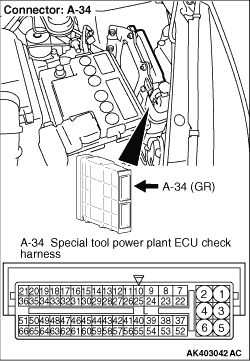
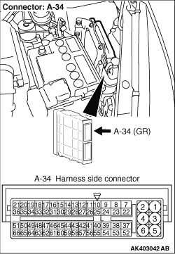
- Disconnect engine-ECU connector, and connect special tool power plant ECU
check harness (MB991987), and then measure the voltage on the check connector.
- Engine: Idling after warm-up
- Transmission: Neutral
- Cooling fan: Not operating
- Voltage between terminal No. 54 and earth.
OK: Switching the headlamps to ON from OFF causes the voltage to decrease.
Q.
Is the check result normal?
Go to Step 13 .
Go to Step 10 .
|
|
Q.
Is the check result normal?
Go to Step 11 .
Repair or replace the connector.
|
|
- Check output line for open/short circuit and damage.
Q.
Is the check result normal?
Go to Step 12 .
Repair the damaged harness wire.
|
|
|
- After alternator is replaced, re-check for trouble symptom.
|
|
|
Q.
Does trouble symptom persist?
|
|
|
Replace the engine-ECU then perform the variant coding (Refer to GROUP 00 - Precautions Before
Service - How to Perform Variant Coding ).
|
|
|
|
|
|
- Remove the spark plug and install to the ignition coil.
- Connect the ignition coil connector.
- Remove all injector connectors.
- At the engine start, check each spark plug procedure a spark.
|
|
|
Q.
Is the check result normal?
|
|
|
Check ignition circuit system (Refer to Inspection Procedure 24 ).
|
|
|
|
|
|
- Check each injector for spray condition (Refer to ).
|
|
|
Q.
Is the check result normal?
|
|
|
- Check compression pressure (Refer to GROUP 11E - On-vehicle Service - Compression
Pressure Check ).
|
|
|
Q.
Is the check result normal?
|
|
|
Repair the compression pressure.
|
|
|
|
|
|
- Check purge control solenoid valve itself (Refer to GROUP 17 - Emission
Control System - Evaporative Emission Control System- Purge Control Solenoid Valve
Check ).
|
|
|
Q.
Is the check result normal?
|
|
|
Replace the purge control solenoid valve.
|
|
|
|
|
|
OK: Operating sounds of fuel pump can be heard.
|
|
|
Q.
Is the check result normal?
|
|
|
Check fuel pump system (Refer to inspection Procedure 22 ).
|
|
|
|
|
|
- After engine-ECU is replaced, re-check for trouble symptom.
|
|
|
Q.
Does trouble system persist?
|
|
|
Check for foreign matters (water, kerosene, etc.) in fuel and replace if necessary.
|
|
|
|
)
)
)