|
|
- Measure battery voltage during cracking.
|
|
|
Q.
Is the check result normal?
|
|
|
 Check battery (Refer to GROUP 54A - Battery - On-vehicle Service - Battery
test Check battery (Refer to GROUP 54A - Battery - On-vehicle Service - Battery
test  ). ).
|
|
|
|
|
|
- Item No. 27: Cranking signal
|
|
|
OK:
ON (Ignition switch: ST)
OFF (Ignition switch: ON)
|
|
|
Q.
Is the check result normal?
|
|
Q.
Is the check result normal?
 Go to Step 4 . Go to Step 4 .
Repair or replace the connector.
|
|
- Disconnect connector, and measure at the harness side.
- Ignition switch: ST
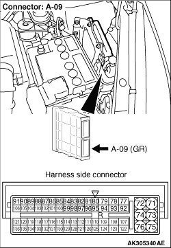
- Voltage between terminal No. 80 and earth.
OK: System voltage
Q.
Is the check result normal?
Go to Step 7 .
Go to Step 5 .
|
|
Q.
Is the check result normal?
Go to Step 6 .
Repair or replace the connector.
|
|
- Check ignition switch (Refer to GROUP 54A - Ignition Switch - Ignition
Switch - Inspection ).
Q.
Is the check result normal?
Check intermediate connector B-117 and repair
if necessary. If intermediate connector is normal, check and repair harness between A-09 (terminal No.
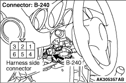
80) engine-ECU connector and B-240 (terminal No. 5) ignition switch connector.
- Check power supply line for open/short circuit.
Replace ignition switch.
|
|
Q.
Is the check result normal?
Go to Step 8 .
Repair or replace the connector.
|
|
| note |
Before checking harness, check intermediate connectors B-117 and repair if necessary.
|
- Check output line for damage.
Q.
Is the check result normal?
Replace the engine-ECU then perform the variant coding (Refer to GROUP 00 - Precautions Before
Service - How to Perform Variant Coding ).
Repair the damaged harness wire.
|
|
Q.
Is the check result normal?
Go to Step 10 .
Repair or replace the connector.
|
|
|
- Check starter cut relay (Refer to GROUP 16 - On-vehicle service - Starter
Relay Check ).
|
|
|
Q.
Is the check result normal?
|
|
|
Replace the starter cut relay.
|
|
|
|
|
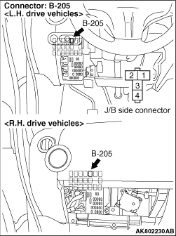
- Remove relay, and measure at J/B side.
- Ignition switch: ON
- Voltage between terminal No. 1 and earth, also between terminal No. 3 and earth.
OK: System voltage
Q.
Is the check result normal?
Go to Step 12 .
Check intermediate connector B-229, and repair
if necessary. If intermediate connector is normal, check and repair harness between B-205 (terminal
No. 1 and terminal No. 3) starter cut relay connector and B-240 (terminal No. 2) ignition switch
connector.
- Check power supply line for open/short circuit.
|
|
Q.
Is the check result normal?
Go to Step 13 .
Repair or replace the connector.
|
|
- Disconnect connector, and measure at harness side.
- Ignition switch: ON
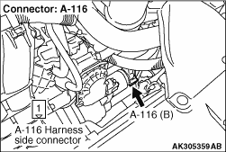
- Voltage between terminal No. 116 and earth.
OK: System voltage
Q.
Is the check result normal?
Go to Step 14 .
Check intermediate connector B-212, and repair
if necessary. If intermediate connector is normal, check and repair harness between B-205 (terminal
No. 2) starter cut relay connector and A-09 (terminal No. 116) engine-ECU connector.
- Check earthing line for open/short circuit.
|
|
Q.
Is the check result normal?
Go to Step 15 .
Repair or replace the connector.
|
|
|
Check starter control relay (Refer to GROUP 16 - On-vehicle service - Starter
Relay Check ).
|
|
|
Q.
Is the check result normal?
|
|
|
Replace the starter control relay.
|
|
|
|
|
- Remove relay, and measure at J/B side.
- Using a jumper wire, connect A-09 (terminal No. 116) engine-ECU connector and earth.
- Ignition switch: ON
- Voltage between terminal No. 3 and earth.
OK: System voltage
Q.
Is the check result normal?
Go to Step 21 .
Go to Step 17 .
|
|
| note |
Before checking harness, check intermediate connectors B-230, B-117 and B-209, and repair
if necessary.
|
- Check power supply line for open/short circuit.
Q.
Is the check result normal?
Go to Step 18 .
Repair the damaged harness wire.
|
|
| note |
Before checking harness, check intermediate connector B-209, and repair if necessary.
|
- Check output line for short circuit.
Q.
Is the check result normal?
Go to Step 19 .
Repair the damaged harness wire.
|
|
| note |
Before checking harness, check intermediate connector B-209, and repair if necessary.
|
- Check earthing line for damage.
Q.
Is the check result normal?
Go to Step 20 .
Repair the damaged harness wire.
|
|
Q.
Is the check result normal?
Go to Step 8 .
Check intermediate connector B-229, and repair
if necessary. If intermediate connector is normal, check and repair harness between B-205 (terminal
No. 1 and terminal No. 3) starter relay connector and B-240 (terminal No. 2) ignition switch
connector.
- Check power supply line for damage.
|
|
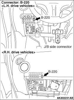
- Remove relay, and measure at J/B side.
- Resistance between terminal No. 2 and earth.
OK: Continuity (2 Ω or less)
Q.
Is the check result normal?
Go to Step 22 .
Check intermediate connector B-231, and repair
if necessary. If intermediate connector is normal, check and repair harness between B-220 (terminal
No. 2) starter control relay connector and body earth.
- Check earthing line for open circuit and damage.
|
|
- Remove relay, and measure at J/B side.
- Ignition switch: ST
- Voltage between terminal No. 1 and earth.
OK: System voltage
Q.
Is the check result normal?
Go to Step 24 .
Go to Step 23 .
|
|
| note |
Before checking harness, check intermediate connectors B-231 and B-117, and repair if
necessary.
|
- Check power supply line for open/short circuit.
Q.
Is the check result normal?
Replace the engine-ECU then perform the variant coding (Refer to GROUP 00 - Precautions Before
Service - How to Perform Variant Coding ).
Repair the damaged harness wire.
|
|
Q.
Is the check result normal?
Go to Step 25 .
Repair or replace the connector.
|
|
- Disconnect A-09 engine-ECU connector
- Disconnect connector, and measure at harness side.
- Ignition switch: ON
- Using a jumper wire, connect A-09 (terminal No. 125 and terminal No. 116) engine-ECU
connector and earth.
- Voltage between terminal No. 1 and earth.
OK: System voltage
Q.
Is the check result normal?
Go to Step 29 .
Go to Step 26 .
|
|
| note |
Before checking harness, check intermediate connectors A-231, B-117 and A-13, and repair
if necessary.
|
- Check power supply line for open/short circuit and damage.
Q.
Is the check result normal?
Go to Step 27 .
Repair the damaged harness wire.
|
|
| note |
Before checking harness, check intermediate connectors A-231, B-117, A-13, and repair
if necessary.
|
- Check output line for short circuit.
Q.
Is the check result normal?
Go to Step 28 .
Repair the damaged harness wire.
|
|
| note |
Before checking harness, check intermediate connectors B-231 and B-117, and repair if
necessary.
|
- Check power supply line for damage.
Q.
Is the check result normal?
Replace the engine-ECU then perform the variant coding (Refer to GROUP 00 - Precautions Before
Service - How to Perform Variant Coding ).
Repair the damaged harness wire.
|
|
| note |
Before checking harness, check intermediate connectors B-231, B-117 and A-13, and repair
if necessary.
|
- Check power supply line for damage.
Q.
Is the check result normal?
Go to Step 30 .
Repair the damaged harness wire.
|
|
| note |
Before checking harness, check intermediate connectors B-230, B-117 and B-209, and repair
if necessary.
|
- Check power supply line for damage.
Q.
Is the check result normal?
Go to Step 31 .
Repair the damaged harness wire.
|
|
Q.
Is the check result normal?
Go to Step 32 .
Repair or replace the connector.
|
|
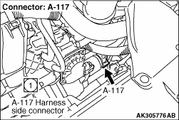
- Disconnect connector, and measure at the harness side.
- Voltage between terminal No. 1 and earth.
OK: System voltage
Q.
Is the check result normal?
Go to Step 33 .
Check and repair harness between A-117 (terminal No.
1) starter connector and battery.
- Check power supply line for open/short circuit.
|
|
- Check power supply line for damage.
Q.
Is the check result normal?
Replace the starter.
Repair the damaged harness wire.
|
)
)
)
)
)
)
)