|
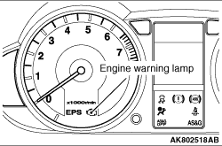
When the abnormal condition occurs with respect to the items of Multipoint Fuel Injection
(MPI) system shown in the table, the engine warning lamp is illuminated. When the lamp remains illuminated
after the engine start, or when the lamp is illuminated while the engine is running, check the
diagnosis code output. There are two methods for checking the indicator lamp burn out: When
the ignition switch is in ON position, the indicator lamp is illuminated, and then extinguished
few seconds later. When the ignition switch is in ON position and the engine starts, the indicator
lamp is extinguished.
|
Code No.
|
Diagnosis item
|
-
|
Engine-ECU
|
P0105*
|
Manifold absolute pressure sensor system
|
P0110*
|
Intake air temperature sensor system <134>
|
P0110
|
Intake air temperature sensor system <3A9>
|
P0115
|
Engine coolant temperature sensor system
|
P0122*
|
Throttle position sensor (main) circuit low input
|
P0123*
|
Throttle position sensor (main) circuit high input
|
P0125*
|
Feedback system monitor
|
P0130
|
Oxygen sensor (front) system
|
P0135
|
Oxygen sensor (front) heater system
|
P0136
|
Oxygen sensor (rear) system
|
P0140
|
Oxygen sensor (rear) circuit no activity detected <3A9>
|
P0141
|
Oxygen sensor (rear) heater system
|
P0170
|
Abnormal fuel system
|
P0201
|
No. 1 injector system
|
P0202
|
No. 2 injector system
|
P0203
|
No. 3 injector system
|
P0222*
|
Throttle position sensor (sub) circuit low input
|
P0223*
|
Throttle position sensor (sub) circuit high input
|
P0300
|
Random/multiple cylinder misfire detected
|
P0301
|
No. 1 cylinder misfire detected
|
P0302
|
No. 2 cylinder misfire detected
|
P0303
|
No. 3 cylinder misfire detected
|
P0325
|
Detonation sensor system
|
P0335*
|
Crank angle sensor system <134>
|
P0335
|
Crank angle sensor system <3A9>
|
P0340
|
Camshaft position sensor system
|
P0420
|
Catalyst malfunction
|
P0443
|
Purge control solenoid valve system
|
P0500
|
Vehicle speed signal system
|
P0513
|
Immobilizer malfunction <134>
|
P0606*
|
Engine-ECU main processor malfunction
|
P0638*
|
Throttle valve control servo circuit range/performance problem
|
P0657*
|
Throttle valve control servo relay circuit malfunction
|
P1603*
|
Battery backup circuit malfunction
|
P1630*
|
Variant coding errors
|
P1961*
|
Trustful check throttle position sensor (main)
|
P1962*
|
Trustful check throttle position sensor (sub)
|
P1963*
|
Trustful check manifold absolute pressure sensor
|
P1964*
|
AD converter
|
P1965*
|
Trustful check accelerator pedal position sensor
|
P1966*
|
Manifold absolute pressure sensor trustful for torque monitoring
|
P1967*
|
Trustful check engine speed
|
P1970*
|
Torque monitoring
|
P1978*
|
Throttle valve control servo malfunction
|
P2100*
|
Throttle valve control servo circuit (open)
|
P2122*
|
Accelerator pedal position sensor (main) circuit low input
|
P2123*
|
Accelerator pedal position sensor (main) circuit high input
|
P2127*
|
Accelerator pedal position sensor (sub) circuit low input
|
P2128*
|
Accelerator pedal position sensor (sub) circuit high input
|
P2135*
|
Throttle position sensor (main and sub) range/performance problem
|
P2138*
|
Accelerator pedal position sensor (main and sub) range/performance
problem
|
U1108
|
Combination meter time-out
|
|
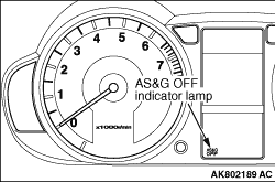
When depressing the Auto Stop & Go (AS&G) OFF switch for the specified
time, the AS&G mode is turned OFF and the AS&G OFF indicator lamp is lit.
When the following items in the table, related to the Auto Stop & Go (AS&G)
system, are abnormal, the AS&G OFF indicator lamp blinks. When the AS&G OFF
indicator lamp continues to blink, check the output of the diagnosis code. After the ignition
switch is turned ON, light the AS&G OFF indicator lamp for several seconds to confirm
whether the lamp is normally operated.
|
Code No.
|
Diagnosis item
|
-
|
Engine-ECU
|
P0105*
|
Manifold absolute pressure sensor system
|
P0110*
|
Intake air temperature sensor system <134>
|
P0110
|
Intake air temperature sensor system <3A9>
|
P0115
|
Engine coolant temperature sensor system
|
P0122*
|
Throttle position sensor (main) circuit low input
|
P0123*
|
Throttle position sensor (main) circuit high input
|
P0125*
|
Feedback system monitor
|
P0130
|
Oxygen sensor (front) system
|
P0135
|
Oxygen sensor (front) heater system
|
P0136
|
Oxygen sensor (rear) system
|
P0140
|
Oxygen sensor (rear) circuit no activity detected <3A9>
|
P0141
|
Oxygen sensor (rear) heater system
|
P0170
|
Abnormal fuel system
|
P0201
|
No. 1 injector system
|
P0202
|
No. 2 injector system
|
P0203
|
No. 3 injector system
|
P0222*
|
Throttle position sensor (sub) circuit low input
|
P0223*
|
Throttle position sensor (sub) circuit high input
|
P0300
|
Random/multiple cylinder misfire detected
|
P0301
|
No. 1 cylinder misfire detected
|
P0302
|
No. 2 cylinder misfire detected
|
P0303
|
No. 3 cylinder misfire detected
|
P0325
|
Detonation sensor system
|
P0335*
|
Crank angle sensor system <134>
|
P0335
|
Crank angle sensor system <3A9>
|
P0340
|
Camshaft position sensor system
|
P0420
|
Catalyst malfunction
|
P0443
|
Purge control solenoid valve system
|
P0500
|
Vehicle speed signal system
|
P0513
|
Immobilizer malfunction <134>
|
P0606*
|
Engine-ECU main processor malfunction
|
P0638*
|
Throttle valve control servo circuit range/performance problem
|
P0657*
|
Throttle valve control servo relay circuit malfunction
|
P1603*
|
Battery backup circuit malfunction
|
P1630*
|
Variant coding errors
|
P1961*
|
Trustful check throttle position sensor (main)
|
P1962*
|
Trustful check throttle position sensor (sub)
|
P1963*
|
Trustful check manifold absolute pressure sensor
|
P1964*
|
AD converter
|
P1965*
|
Trustful check accelerator pedal position sensor
|
P1966*
|
Manifold absolute pressure sensor trustful for torque monitoring
|
P1967*
|
Trustful check engine speed
|
P1970*
|
Torque monitoring
|
P1978*
|
Throttle valve control servo malfunction
|
P2100*
|
Throttle valve control servo circuit (open)
|
P2122*
|
Accelerator pedal position sensor (main) circuit low input
|
P2123*
|
Accelerator pedal position sensor (main) circuit high input
|
P2127*
|
Accelerator pedal position sensor (sub) circuit low input
|
P2128*
|
Accelerator pedal position sensor (sub) circuit high input
|
P2135*
|
Throttle position sensor (main and sub) range/performance problem
|
P2138*
|
Accelerator pedal position sensor (main and sub) range/performance
problem
|
U1108
|
Combination meter time-out
|
|
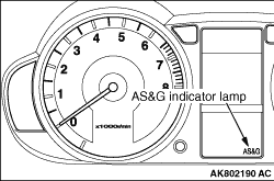
When the specified conditions are satisfied during the engine operation, the engine-ECU
stops the engine. At that time, the AS&G indicator lamp is lit. If the following items
in the table, related to the Auto Stop & Go (AS&G) system, are applied, the AS&G
indicator lamp blinks. When the AS&G indicator lamp continues to blink, carry out the
check according to the applied item. After the ignition switch is turned ON, light the AS&G indicator
lamp for several seconds to confirm whether the lamp is normally operated.
|
|
|
Refer to  , GROUP 00 - How to Use Troubleshooting/Inspection
Service Points - Diagnosis Function. , GROUP 00 - How to Use Troubleshooting/Inspection
Service Points - Diagnosis Function.
|
|
|
1.Carry out inspection by means of the data list and the actuator test function, if
there is an abnormality, check and repair the chassis harness and components.
|
|
|
2.After repairing, re-check using the M.U.T.-III and check that the abnormal input and
output have returned to normal as a result of the repairs.
|
|
|
3.Erase the diagnosis code memory.
|
|
|
4.Remove the M.U.T.-III, and then start the engine again and carry out a road test to
confirm that the problem has disappeared.
|
|
|
When determining the malfunction and storing the diagnosis code, the engine-ECU stores
the sensor input status, the control status and so on for each of the diagnosis codes at the time
of malfunction detection. This function’s data are called "Freeze Frame" data.
|
|
|
The each diagnosis code has two blocks for storing the freeze frame data. The block 1
and 2 store the same data at the first detection. After the engine-ECU judges the first detected malfunction
to have been corrected by change in some circumstances, the malfunction is detected again, whose
data the block 2 can store. Whenever this is repeated again, the freeze frame data are updated
and stored in the block 2.
|
|
|
By analyzing these freeze frame data with the M.U.T.-III, an effective troubleshooting
can be performed.
|
|
|
The display items of freeze frame data are shown below.
|
|
|
The engine-ECU monitors the following main diagnosis items, judges if these items are
in good condition or not, and the stores its history. this history can be read out by using
M.U.T.-III. (If the ECU has judged a item before, the M.U.T.-III displays "Completed").
|
|
|
In addition, if diagnosis codes are erased or the battery cable is disconnected, this
history will also be erased (the memory will be reset).
|
|
|
Continuously monitoring
- Comprehensive Component Monitor (Sensor and actuator)
- Fuel System Monitoring: P0170
- Misfire Monitoring: P0300
|
|
|
Non-continuously monitoring
- EGR System Monitoring: Not supported
- Oxygen Sensor Monitoring: P0130, P0136
- Oxygen Sensor Heater Monitoring: P0135, P0141
- A/C Refrigerant Monitoring: Not supported
- Secondary Air System Monitoring: Not supported
- Evaporative System Monitoring: Not supported
- Heated Catalyst Monitoring: Not supported
- Catalyst Monitoring: P0420
|
Malfunctioning item
|
Control contents during malfunction
|
Intake air temperature sensor
|
Controls as if the intake air temperature is 25°C.
|
Manifold absolute pressure sensor
|
Uses the throttle position sensor signal and engine speed signal
(crank angle sensor signal) to take reading of the basic injector drive time and basic ignition timing
from the pre-set mapping.
|
Throttle position sensor (main)
|
- Controls the throttle valve position through the use
of the throttle position sensor (sub) signal.
- Renders the amount of accelerator pedal travel as being approximately one-half the
normal opening angle.
- Prohibits the operation of the engine speed feedback control.
- Cuts off fuel when the engine speed exceeds 3,000 r/min.
- Suppresses the engine output by stopping the electronic-controlled throttle valve
system if the throttle position sensor (sub) is also malfunctioning.
|
Throttle position sensor (sub)
|
- Controls the throttle valve position through the use
of the throttle position sensor (main) signal.
- Renders the amount of accelerator pedal travel as being approximately one-half the
normal opening angle.
- Cuts off fuel when the engine speed exceeds 3,000 r/min.
- Suppresses the engine output by stopping the electronic-controlled throttle valve
system if the throttle position sensor (main) is also malfunctioning.
|
Accelerator pedal position sensor (main)
|
- Detects the amount of the accelerator pedal travel through
the use of the accelerator pedal position sensor (sub) signal, but rendering it only as being approximately
one-half the normal opening angle.
- Cuts off fuel when the engine speed exceeds 3,000 r/min.
- Suppresses the engine output by stopping the electronic-controlled throttle valve
system if the accelerator pedal position sensor (sub) is also malfunctioning.
|
Accelerator pedal position sensor (sub)
|
- Detects the amount of the accelerator pedal travel through
the use of the accelerator pedal position sensor (main) signal, but rendering it only as being approximately
one-half the normal opening angle.
- Cuts off fuel when the engine speed exceeds 3,000 r/min.
- Suppresses the engine output by stopping the electronic-controlled throttle valve
system if the accelerator pedal position sensor (main) is also malfunctioning.
|
Engine coolant temperature sensor
|
Controls as if the engine coolant temperature is 80°C. (This
control will be continued until the ignition switch is turned to the "LOCK" (OFF) position even though
the sensor signal returns to normal.)
|
Camshaft position sensor
|
Injects fuel into the cylinders in the order 1-3-2 with irregular
timing. (After the ignition switch is turned to the "ON" position, the No. 1 cylinder top dead
center is not detected at all.)
|
Oxygen sensor <front>
|
Air/fuel ratio closed loop control is not performed.
|
Oxygen sensor <rear>
|
Performs the closed loop control of the air/fuel ratio by
using only the signal of the oxygen sensor (front) installed on the front side of the catalytic
converter.
|
Detonation sensor
|
Switches the ignition timing from ignition timing for high octane
to ignition timing for standard octane fuel.
|
Neutral position sensor <Vehicles with AS&G system>
|
In the normal operation, the auto stop is prohibited. If the malfunction
is detected during the auto stop, the auto start is prohibited.
|
Clutch switch (A) <Vehicles with AS&G system>
|
In the normal operation, the auto stop is prohibited.
|
Clutch switch (B) <Vehicles with AS&G system>
|
In the normal operation, the auto stop is prohibited.
|
Starter cut relay monitor <Vehicles with AS&G system>
|
In the normal operation, the auto stop is prohibited. If the malfunction
is detected during the auto stop, the auto start is prohibited.
|
Brake vacuum sensor <Vehicles with AS&G system>
|
In the normal operation, the auto stop is prohibited. If the malfunction
is detected during the auto stop, the auto start is prohibited.
|
Battery current sensor <Vehicles with AS&G system>
|
In the normal operation, the auto stop is prohibited. If the malfunction
is detected during the auto stop, the auto start is prohibited.
|
Battery temperature sensor <Vehicles with AS&G system>
|
In the normal operation, the auto stop is prohibited. If the malfunction
is detected during the auto stop, the auto start is prohibited.
|
Ignition coil (incorporating power transistor)
|
Cuts off the fuel supply to cylinders with an abnormal ignition.
|
Alternator FR terminal
|
Does not control the output of the alternator according to an electrical
load. (works as a normal alternator)
|
Misfiring
|
If the detected misfiring causes damage to the catalyst, the misfiring
cylinder will be shut down.
|
Throttle valve position feedback
|
- Suppresses the engine output by stopping the electronic-controlled
throttle valve system.
- Prohibits the operation of the engine speed feedback control.
|
Throttle valve control servo
|
- Suppresses the engine output by stopping the electronic-controlled
throttle valve system.
- Prohibits the operation of the engine speed feedback control.
|
Engine-ECU main processor
|
- Suppresses the engine output by stopping the electronic-controlled
throttle valve system.
- Prohibits the operation of the engine speed feedback control.
|
Communication between powertrain control module main processor and
system LSI
|
- Renders the amount of accelerator pedal travel as being
approximately one-half the normal opening angle.
- Prohibits the operation of the engine speed feedback control.
- Cuts off fuel when the engine speed exceeds 3,000 r/min.
|
Intake air monitor
|
- Suppresses the engine output by stopping the electronic-controlled
throttle valve system.
- Prohibits the operation of engine speed feedback.
|
)
)
)
)
)
)