|
|
Measure the valve clearance as illustrated.
|
|
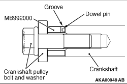
Set the special tool Crankshaft adapter (MB992000) to the crankshaft, and install the
crankshaft pulley bolt and washer.
|
|
1.
| caution |
The crankshaft should always be rotated clockwise.
|
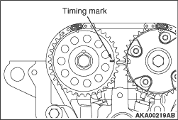
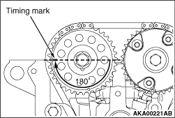
Rotate the crankshaft clockwise until the mark on the camshaft sprocket is aligned with
the mark on the upper surface of cylinder head. (Set the No. 1 cylinder to TDC on the compression
stroke.)
|
|
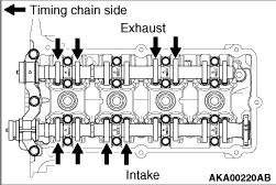
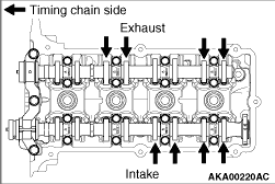
2.Now, the valve clearance (shown with an arrow) can be measured.
|
|
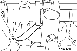
3.Using a thickness gauge, measure the clearance between the cam base circle and the valve
tappet.
Standard value (cold engine)
Inlet valve: 0.22 ± 0.04 mm
Exhaust valve: 0.30 ± 0.04 mm
4.If the measured value does not conform to the standard value, record the measured
value.
|
|
5.Rotate the crankshaft clockwise until the mating mark on the camshaft sprocket comes to
the illustrated location. This will bring the No. 4 cylinder to TDC on the compression stroke.
|
|
6.Measure the valve clearance at the location shown with an arrow.
7.If the measured value does not conform to the standard value, record the measured
value.
8.Replace the valve tappet for the valve whose clearance is out of the standard value.
| note |
Valve tappets are available in 31 sizes, at 0.02 mm intervals in the 5.10 - 5.70
mm range.
|
|
|
9.Valve tappets should be selected in the following manner.
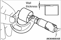
(1)
Remove the valve tappet and measure its thickness.
(2)
Calculate the correct thickness for a new valve tappet as follows that achieves the
standard valve clearance.
A: Thickness of new valve tappet
B: Thickness of old valve tappet
C: Measured valve clearance
Equation:
Inlet valve A = B + (C - 0.22 mm)
Exhaust valve A = B + (C - 0.30 mm)
For removal and installation procedures for the valve tappet, refer to "CAMSHAFT REMOVAL
AND INSTALLATION."
(Refer to Camshaft Removal and Installation. ) )
|
|
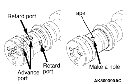
1.Seal with a tape all the intake camshaft ports for the advanced angle and the retarded
angle.
2.Make a hole on the port for the advanced angle.
|
|
| caution |
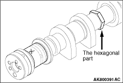
Fix the camshaft on a vise not to damage it.
|
3.Fixing the hexagonal area of the intake camshaft on a vise, install the V.V.T. sprocket.
|
|
| caution |
When applying air pressure, keep in mind that oil could splash.
|
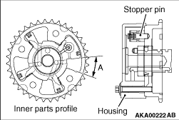
4.By applying air pressure slowly to the holed port for the advanced angle, remove the
stopper pin.
5.Turn the V.V.T. sprocket housing in the right and left directions. Check it smoothly
moves in the range of A (approximately 25°)
| note |
The stopper pin is locked in the most retarded angle position.
|
6..After the check, remove the V.V.T. sprocket from the intake camshaft
7.Completely remove the tape sealing the intake camshaft ports for the advanced angle
and for the retarded angle.
|
)
)
)
)
)
)
)
)
)
)