|
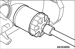
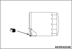
1.Remove the oil filter using an oil filter wrench (commercially available).
|
|
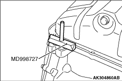
1.Remove the oil pan retaining bolts.
2.Knock the special tool Oil pan cutter (MD998727) between the oil pan and the cylinder
block.
|
|
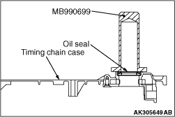
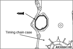
Install the front oil seal into the timing chain case using the special
tool Differential oil seal installer (MB990699).
|
|
|
1.Remove any liquid gasket remaining on the timing chain case, the cylinder block, and
the cylinder head.
|
|
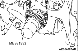
2.Install the special tool Oil seal guide (MB991993) onto the crankshaft.
|
|
| caution |
The timing chain case should be installed within 3 minutes of
applying liquid gasket.
|
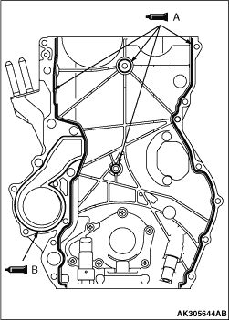
3.Apply a 2.0 ± 0.5 mm bead of liquid gasket to location A, and a 1.5 ± 0.5
mm bead of liquid gasket to location B on the timing chain case respectively as illustrated.
Specified sealant:
Three bond 1217G or equivalent
4.Install the timing chain case.
|
|
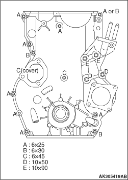
5.
| note |
The retaining bolts have different lengths. Be sure to use the correct bolt for each location.
|
Tighten the chain case retaining bolts to the specified torques.
Tightening torque:
M6 8.4 ± 0.6 N·m
M10 (at support bracket) 39.5 ± 3.0 N·m
M10 (at brace) 36 ± 3.6 N·m
|
|
|
1.Remove any liquid gasket remaining on the cylinder block, the timing chain case, the
oil seal case and the oil pan.
|
|
| caution |
The oil pan should be installed within 3 minutes of applying
liquid gasket.
|
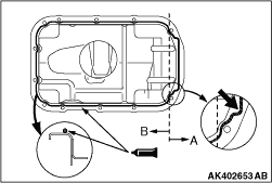
2.Apply a 4.0 ± 0.5 mm bead of liquid gasket to location A, and a 2.0 ± 0.5
mm bead of liquid gasket to location B on the oil pan respectively as illustrated.
Specified sealant:
Three bond 1217G or equivalent
3.Install the oil pan by tightening the fittings to 7.6 ± 0.6 N·m.
|
|
|
1.Remove any liquid gasket remaining on the cylinder head cover, the timing chain case
and the cylinder head.
|
|
| caution |
The timing chain should be installed within 3 minutes of applying
liquid gasket.
|
2.Apply a 4 mm bead of liquid gasket as illustrated.
Specified sealant:
Three bond 1217G or equivalent
|
|
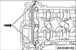
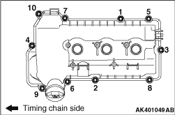
3.In accordance with the procedure shown in Figure, tighten the bolt of the cylinder head
cover to 9.0 ± 1.0 N·m.
|
|
|
1.Remove any liquid gasket remaining on the timing chain case and the cover.
|
|
| caution |
The cover should be installed within 3 minutes of applying liquid
gasket.
|
2.Apply a 2.0 ± 0.5 mm bead of liquid gasket as illustrated.
Specified sealant:
Three bond 1217G or equivalent
|
|
|
1.Clean the filter mounting surface on the cylinder block.
|
|
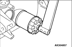
2.Apply engine oil to the oil filter gasket as shown in the drawing.
|
|
3.
| caution |
Tighten the oil filter using a filter wrench (commercially available).
Manual tightening cannot generate the required torque, leading to oil leakage.
|
Screw in the oil filter until the O-ring contacts the mounting surface. Further tighten
by 3/4 of a turn or to 11 ± 1 N·m using a filter wrench.
|
)

)
)
)
)
)
)
)
)
)
)
)
)