|
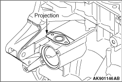
Place the water pipe assembly gasket onto the cylinder block, facing
the gasket’s protruded portion in the illustrated direction.
|
|
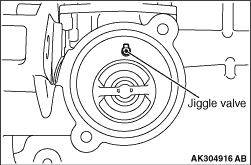
Install the thermostat onto the cylinder block such that the jiggle valve
is positioned on top of the thermostat housing.
|
|
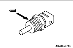
1.Remove any sealant that may be remaining on the coolant temperature sensor or the threaded
hole in the cylinder head.
2.Apply sealant onto the threaded portion (illustrated) of the sensor.
Specified sealant:
LOCTITE 262 or equivalent
3.Install the coolant temperature sensor onto the cylinder block by tightening it to
30 ± 9 N·m.
|
|
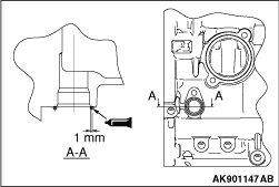
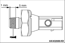
1.Remove any sealant that may be remaining on the angle sensor or the mounting face on the
cylinder block.
2.Apply a bead of sealant with a diameter of 1.7 ± 0.5 mm on the cylinder block
as illustrated.
Specified sealant:
Three bond 1207F or equivalent
3.Install the crank angle sensor onto the cylinder block by tightening it to 9.5 ± 2.5
N·m.
|
|
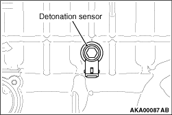
Align the detonation sensor connector with the position shown in the illustration, and
then tighten it to the specified torque of 20 ± 2 N·m.
|
|
1.Remove any sealant that may be remaining on the engine oil pressure switch or the threaded
hole in the cylinder block.
2.Apply sealant to the threaded portion of the engine oil pressure switch as illustrated.
Specified sealant:
Three bond 1215 or equivalent
3.Install the engine oil pressure switch onto the cylinder block by tightening it to
10 ± 2 N·m.
|
|
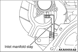
1.After making sure that the inlet manifold stay is in close contact with the inlet manifold
and the cylinder block, temporarily tighten the inlet manifold stay.
2.Check whether the sealing surface securely touch each other.
3.Tighten the bolts to the specified torque of 19 ± 1 N·m.
|
)

)
)
)
)
)
)
)