|
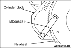
1.Lock the flywheel using the special tool Flywheel stopper (MD998781).
2.Remove the flywheel bolt.
|
|
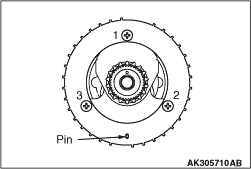
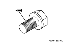
1.Apply engine oil to the crankshaft sensing ring screw.
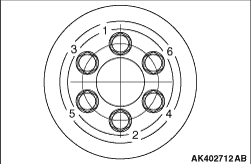
2.Tighten the crankshaft sensing ring screws to 9.0 ± 1.0 N·m in the
steps given in the illustrated.
|
|
|
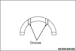
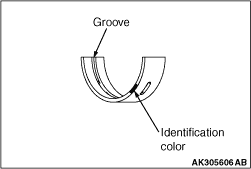
1.Install the thrust bearing onto the cylinder block side of the No. 4 bearing. Apply
engine oil to the thrust bearing to facilitate installation.
|
|
2.The thrust bearing should be installed such that its groove faces the crankshaft weight.
|
|
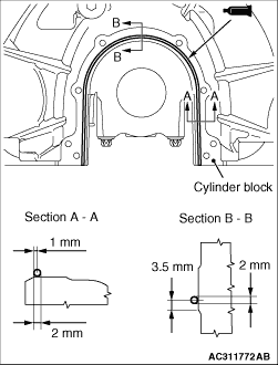
1.The crankshaft bearing upper should be selected based on the identification mark on the
bottom face of the cylinder block (illustrated) and the table shown below.
Every crankshaft bearing upper is identified by the paint mark at the illustrated location.
|
|
Cylinder block
|
Crankshaft bearing paint color
|
Identification mark
|
Journal diameter
mm
|
1
|
50.000 - 50.005
|
Green
|
2
|
50.005 - 50.010
|
Yellow
|
3
|
50.010 - 50.015
|
Red
|
|
|
|
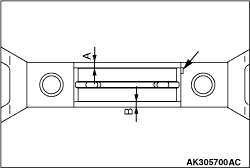
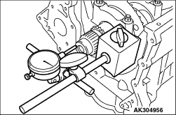
2.Select and install the crankshaft bearing upper.
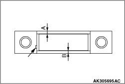
3.Measure the illustrated location. The error should be within 0.5 mm.
In case of the service part, install it aligning the bearing projection with the places
shown in Figure.
|
|
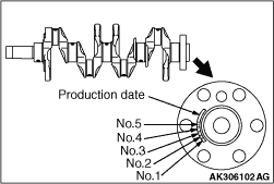
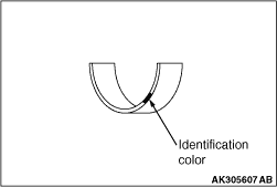
1.The crankshaft bearing lower should be selected based on the identification mark on the
crankshaft rear flange (illustrated) and the table shown below.
|
|
2.Every crankshaft bearing lower is identified by the paint mark at the illustrated location.
|
|
Crankshaft
|
Crankshaft bearing paint color
|
Identification mark
|
Journal diameter
mm
|
P
|
46.024 - 46.029
|
Green
|
Y
|
46.019 - 46.024
|
Yellow
|
N
|
46.014 - 46.019
|
Red
|
W
|
46.009 - 46.014
|
White
|
B
|
46.004 - 46.009
|
Purple
|
|
|
|
3.Select and install the crankshaft bearing lower.
4.Measure the illustrated location. The error should be within 0.5 mm.
In case of the service part, install it aligning the bearing projection with the places
shown in Figure.
|
|
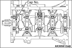
1.Install the bearing cap, based on the identification mark at the illustrated location.
|
|
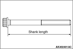
2.Before the bearing cap bolt is installed, make sure the nominal length of the bolt is
below the limit. If above the limit, replace the bolt with the new one.
Standard value: 75.3 mm
3.Apply engine oil to the threaded portion and seating face of the bolt.
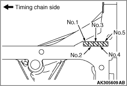
4.Tighten the bearing cap bolts in the illustrated sequence to 35 ± 2 N·m.
|
|
5.
| caution |
- If the bolt is tightened
less than the specified lower limit of 60 degree angle, the bolt may become loose. Be sure to
tighten correctly.
- If the bolt is tightened in excess of the specified upper limit of 64 degree angle,
loosen the nut completely and repeat the entire procedures.
|
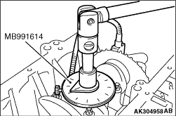
Using the special tool Angle gauge (MB991614), tighten the bearing cap bolts in the illustrated
sequence by a further 60 to 64 degree angle.
|
|
6.With the bearing caps installed, check the crankshaft end play. If the measured value
exceeds the limit, replace the crankshaft bearings.
Standard value: 0.09 - 0.27 mm
Limit: 0.30 mm
|
|
|
1.Remove sealant from the crankshaft rear oil seal case assembly mounting surface of
the cylinder block.
|
|
|
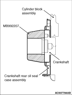
2.Apply a small amount of engine oil to the outer diameter of special tool oil seal
guide (MB992207).
|
|
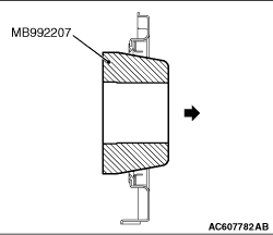
3.Pass the special tool through the crankshaft rear oil seal case assembly in the direction
shown in the figure (opposite to the direction of the crankshaft rear oil seal case assembly installation).
| note |
This adjusts the direction of the oil seal lip.
|
|
|
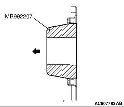
4.Install the special tool to the crankshaft rear oil seal case assembly in the opposite
direction from the direction in Step 3 (in the direction of the crankshaft rear oil seal case assembly
installation).
|
|
5.Apply a bead of specified sealant to the crankshaft rear oil seal case assembly mating
surface of the cylinder block as shown.
Specified sealant:
Three bond 1217G or equivalent
|
|
6.Install the special tool to the crankshaft.
7.
| caution |
Install the crankshaft rear oil seal case assembly not
to damage the crankshaft rear oil seal.
|
Within 3 minutes after applying the specified sealant, install the crankshaft rear oil
seal case assembly to the cylinder block.
8.Tighten the crankshaft rear oil seal case assembly mounting bolts to the specified
torque.
Tightening torque: 7.6 ± 0.6 N·m
|
|
|
1.Remove any sealant remaining on the flywheel bolt or the threaded hole in the crankshaft.
|
|
2.
| caution |
Apply sealant correctly so that it will not be squeezed out onto
the end of the threaded portion upon assembly.
|
Apply sealant to the threaded portion of the flywheel bolt as illustrated.
Specified sealant:
LOCTITE 2701 or equivalent
|
|
3.Fix the flywheel in place using the special tool Flywheel stopper (MD998781).
|
|
4.In accordance with the numerical order shown in the illustration, tighten
the drive plate bolt to the specified torque of 100 ± 5 N·m in several steps.
|
)

)
)
)
)
)
)
)
)
)
)
)
)
)
)
)
)
)
)
)